Device description
3D view
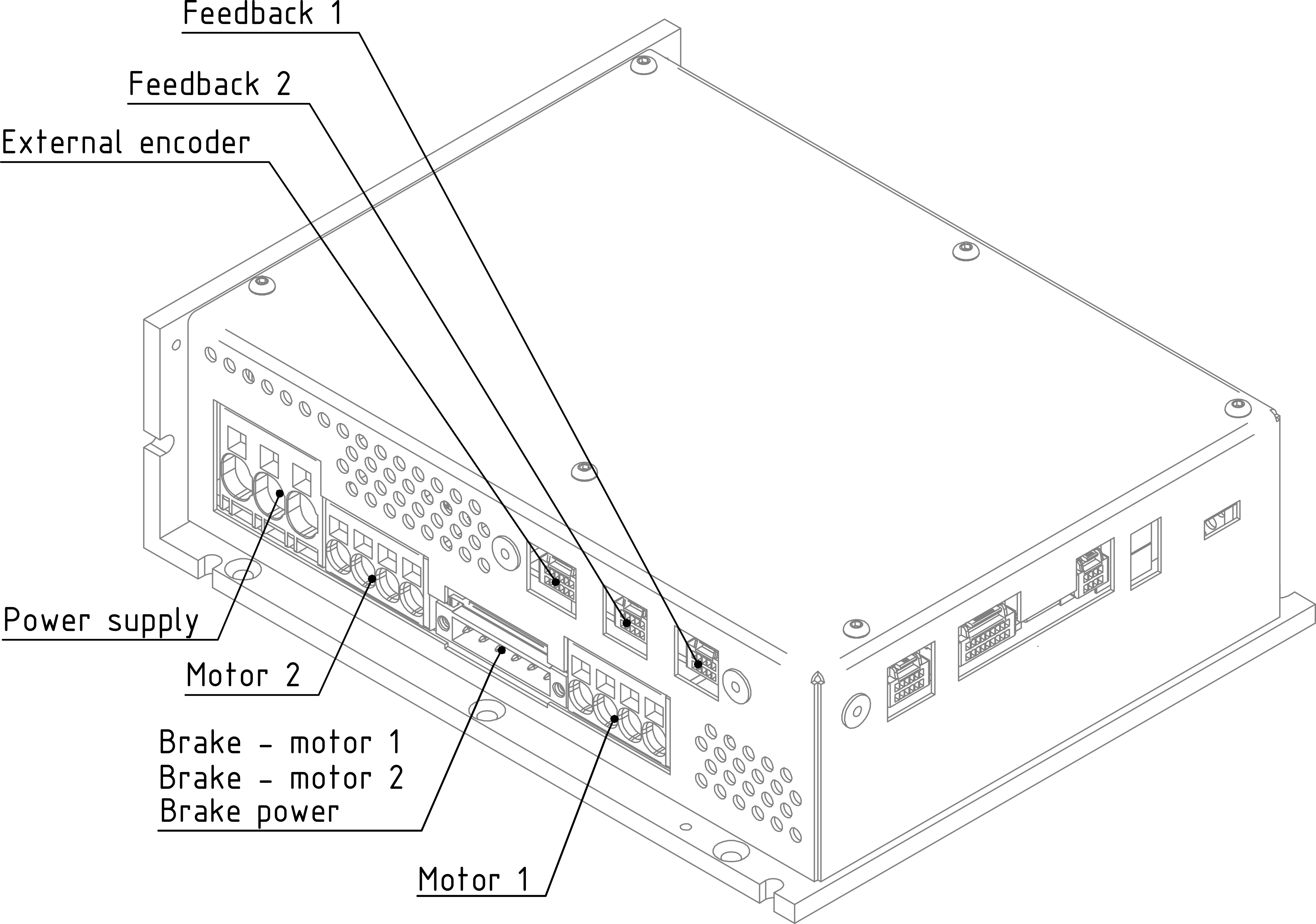
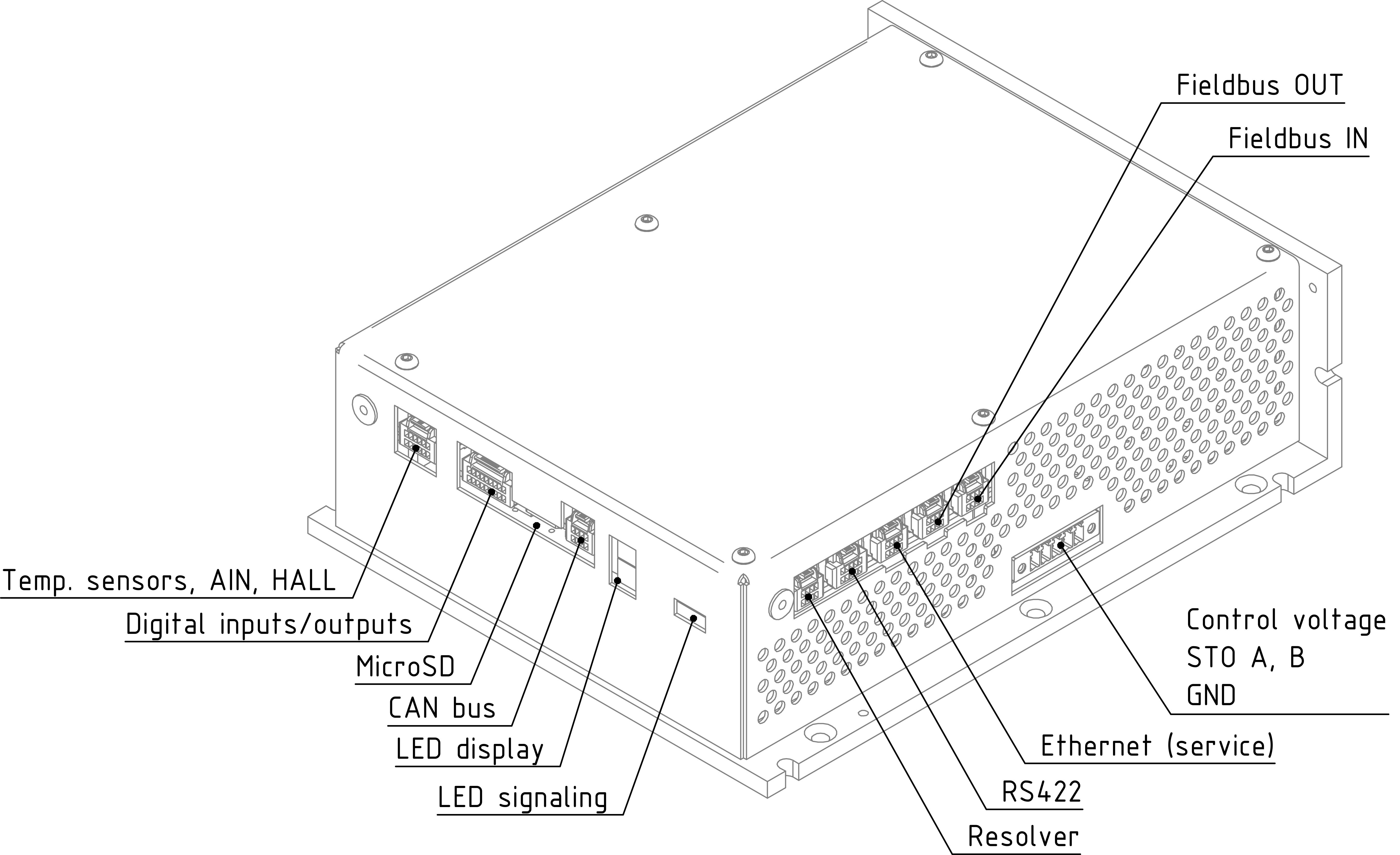
Description of communication, input/output and control
Communication interfaces
- Ethernet 100/1000 Mb/s with UDP protocol, designed for parameter recording, monitoring, testing, but also online control;
- CAN bus protocol can be modified according to customer requirements;
- Ethernet 100/1000 Mb/s with optional protocol, programmed in the gate array and designed for connection of fast industrial buses for real-time control. Currently, this interface is equipped with the EtherCAT protocol (only for standard firmware); according to customer requirements it can be modified to another type of protocol.
- RS422 or RS485, data transfer via unused servomotor feedback interface. It can be used for communication with devices based on RS422 or RS485 standard (encoder, gyro, master controller, other system, etc.). This interface enables high-speed communication up to 20Mbit/s.
Inputs / outputs
The built-in TGZ servo amplifiers have 8 isolated digital inputs, 6 isolated digital outputs, 1 analog input 0-10V, 2 PT1000 thermistor inputs and 3 special Hall sensor inputs implemented. It is possible to read/control these inputs/outputs using a user program (C language):
| I/O | Type | Count | Value |
|---|---|---|---|
| input | analog | 1 | 0-10 V |
| input | thermistor | 2 | standard PT1000 |
| input | Hall | 3 | 5-30 V |
| input | isolated digital | 8 | 0-24 V (0-10 V low / 13-24 V high), 10 mA |
| output | isolated digital | 6 | 5-24 V, 300 mA / max. output |
The servo amplifier has four feedback connectors, which have a wide range of uses. In addition to motor feedback, they can be used to connect devices operating on the principle of the RS422 or RS485 standard.
| Type | Standard | Interface | Examples of Possible Connected Devices |
|---|---|---|---|
| FB1 | RS422/RS485 | Hiperface DSL, EnDat 2.2, SSI, BISS | Absolute magnetic/optical encoder, incremental magnetic/optical encoder with Hall sensors 2, gyroscope |
| FB2 | RS422/RS485 | Hiperface DSL, EnDat 2.2, SSI, BISS | Absolute magnetic/optical encoder, incremental magnetic/optical encoder with Hall sensors 2, gyroscope |
| FE1 | RS422/RS485 | Hiperface DSL, EnDat 2.2, SSI, BISS | Absolute magnetic/optical encoder, incremental magnetic/optical encoder with Hall sensors 2, gyroscope |
| FB31 | 2 × full-duplex RS422 | - | Control system |
| FB4 | Resolver | Analog | Various resolver position sensors |
- Hiperface DSL – digital communication, sensors are manufactured with a resolution of 15 to 24 bits per revolution (multi-speed design – 4,096 revolutions). This type of feedback is used for motors with a single connector or cable.
- EnDat 2.2 – digital communication, sensors are manufactured with a resolution of 18 to 25 bits per revolution (multi-speed design – 4,096 revolutions).
- SSI – encoders with synchronous system interface.
- BISS – sensors with BISS-C protocol.
Control
TGZ servoamplifiers can be controlled:
- digital control via EtherCAT, CAN-bus (torque, speed, position profiles, etc.) and via Ethernet UDP protocol;
- via user program (language C) – digital inputs, analog voltage, etc.
Connectors
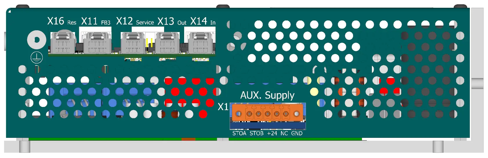
View of the ENET/ECAT side
-
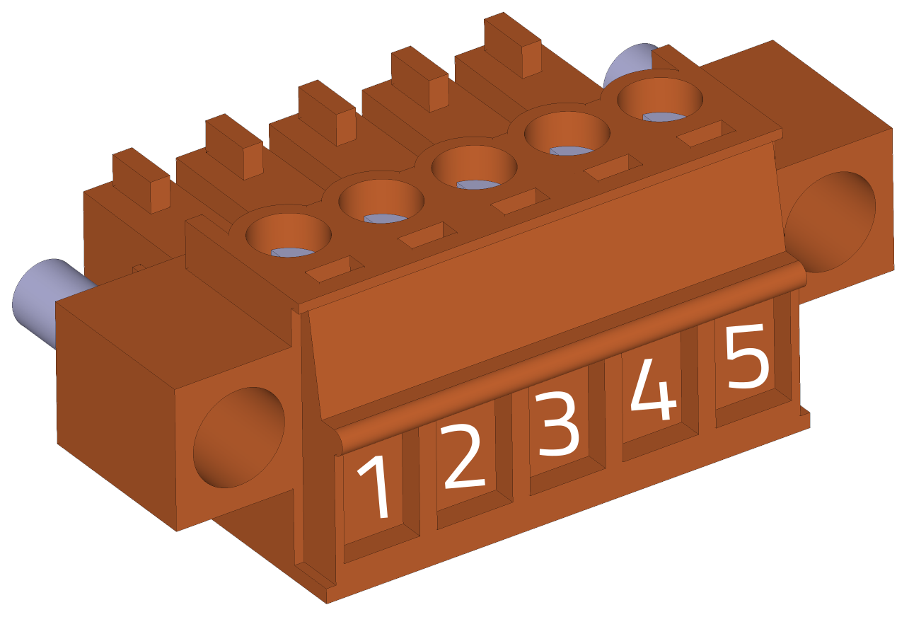
X1 - Control supply voltage
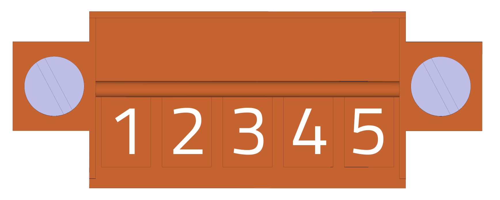
Housing back side view (wire side):
-
Weidmüller BCZ 3.81/05/180F SN OR BX
pin # Marking Description AWG 1 STO_A STO channel A 16 2 STO_B STO channel B 16 3 VCC +24V control supply 16 4 NC No connect 16 5 GND GND (0 V) 16 EMI suppression
Please pay attention to the installation of the suppression toroidal core according to the instructions.
-
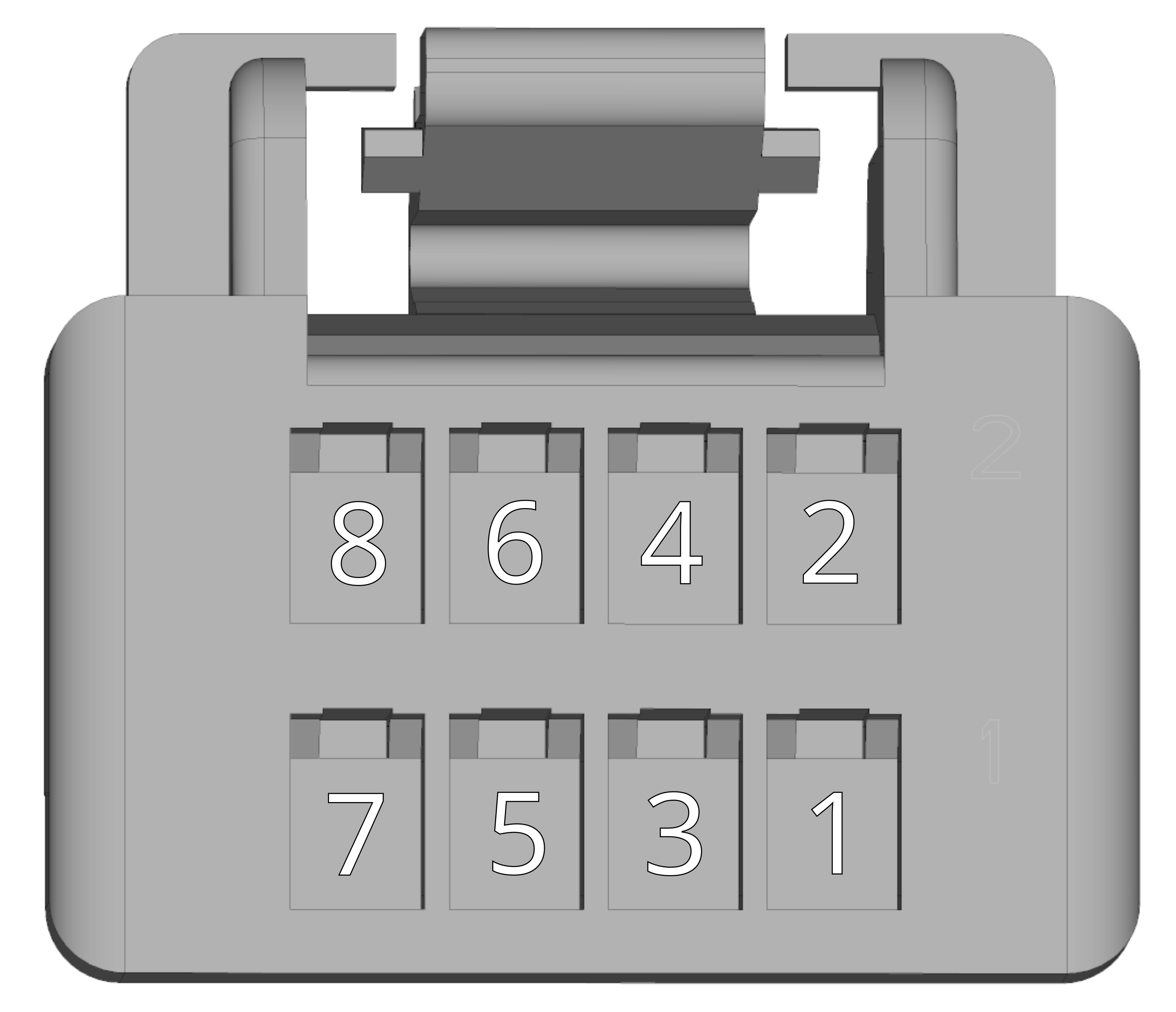
X16 - Feedback 4 - resolver
-
Molex ClikMate 5031490800 - recommended crimping contacts Molex 502579 3
pin # Marking Description 1 R2 Resolver excitation + 2 R1 Resolver excitation - 3 S1 SIN + resolver output 4 S3 SIN - resolver output 5 S2 COS + resolver output 6 S4 COS - resolver output 7 AGND Internal analog ground 8 AGND Internal analog ground For details about resolver input please see Common HW section.
-
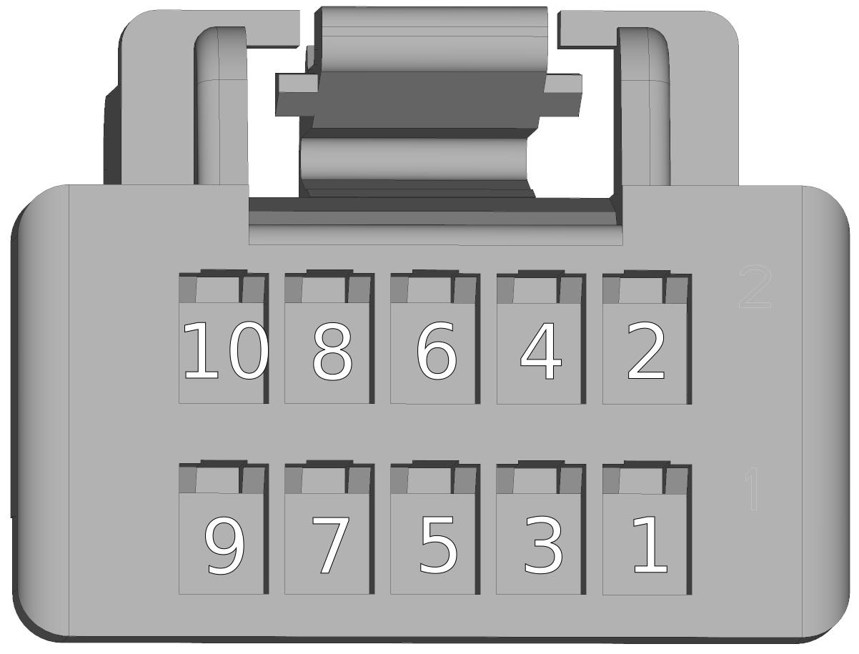
X11 - Feedback 3 - RS422
-
Molex ClikMate 5031491000 - recommended crimping contacts Molex 502579 3
pin # Marking Description 1 TxD- RS422 #1 Transmit data - 2 TxD+ RS422 #1 Transmit data + 3 RxD- RS422 #1 Recieve data - 4 RxD+ RS422 #1 Recieve data + 5 +12 VDC OUT output +12V 6 GND Common GND 7 TxD+ RS422 #2 Transmit data + 8 TxD- RS422 #2 Transmit data - 9 RxD+ RS422 #2 Recieve data + 10 RxD- RS422 #2 Recieve data - Warning
When using this type of feedback, make sure you are using the appropriate TGZ firmware that supports these features.
-
X12 - Ethernet UDP - service
-
Molex ClikMate 5031490800 - recommended crimping contacts Molex 502579 3
pin # Marking Description 1 DD+ T568B pair D positive (Bn-Wh) 2 DD- T568B pair D negative (Bn) 3 DC- T568B pair C negative (Bl-Wh) 4 DC+ T568B pair C positive (Bl) 5 DB- T568B pair B negative (Gn) 6 DB+ T568B pair B positive (Gn-Wh) 7 DA+ T568B pair A positive (Or-Wh) 8 DA- T568B pair A negative (Or) -
X13 - EtherCAT 2 - Fieldbus out
-
Molex ClikMate 5031490800 - recommended crimping contacts Molex 502579 3
pin # Marking Description 1 DD+ T568B pair D positive (Bn-Wh) 2 DD- T568B pair D negative (Bn) 3 DC- T568B pair C negative (Bl-Wh) 4 DC+ T568B pair C positive (Bl) 5 DB- T568B pair B negative (Gn) 6 DB+ T568B pair B positive (Gn-Wh) 7 DA+ T568B pair A positive (Or-Wh) 8 DA- T568B pair A negative (Or) -
X14 - EtherCAT 1 - Fieldbus in
-
Molex ClikMate 5031490800 - recommended crimping contacts Molex 502579 3
pin # Marking Description 1 DD+ T568B pair D positive (Bn-Wh) 2 DD- T568B pair D negative (Bn) 3 DC- T568B pair C negative (Bl-Wh) 4 DC+ T568B pair C positive (Bl) 5 DB- T568B pair B negative (Gn) 6 DB+ T568B pair B positive (Gn-Wh) 7 DA+ T568B pair A positive (Or-Wh) 8 DA- T568B pair A negative (Or)
View of the CAN/IO/SD Side
-
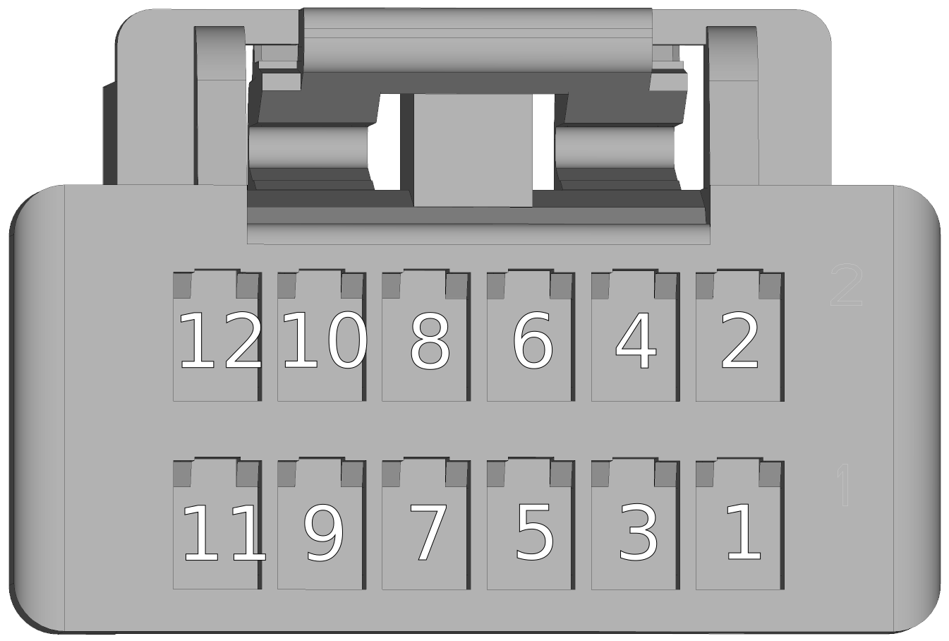
X7 - Hall + Analog inputs
-
Molex ClikMate 5031491200 - recommended crimping contacts Molex 502579 3
pin # Marking Description Range 1 AIN Analog input 0-10V 0~10V 2 AGND Analog ground 0V 3 PT1000_2 input for 2. PT1000 0~5V 4 PT1000_2 input for 2. PT1000 0V 5 PT1000_1 input for 1. PT1000 0~5V 6 PT1000_1 input for 1. PT1000 0V 7 HALL1 Hall 1 signal 5~30V 8 HGND Hall common ground 0V 9 HALL2 Hall 2 signal 5~30V 10 VHO Hall output power (fused) 5~30V 11 HALL3 Hall 3 signal 5~30V 12 VHI Hall input power 5~30V For details about Hall inputs please see Common HW section.
-
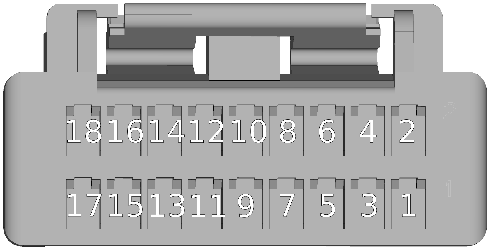
X8 - Digital I/O
-
Molex ClikMate 5031491800 - recommended crimping contacts Molex 502579 3
pin # Marking Description 1 DI1 Digital input isolated no. 1 2 DI2 Digital input isolated no. 2 3 DI3 Digital input isolated no. 3 4 DI4 Digital input isolated no. 4 5 DI5 Digital input isolated no. 5 6 DI6 Digital input isolated no. 6 7 DI7 Digital input isolated no. 7 8 DI8 Digital input isolated no. 8 9 GNDIO Isolated power ground 10 GNDIO Isolated power ground 11 VDDIO Isolated PSU DO 24V 12 VDDIO Isolated PSU DO 24V 13 DO1 Digital output isolated no. 1 14 DO2 Digital output isolated no. 2 15 DO3 Digital output isolated no. 3 16 DO4 Digital output isolated no. 4 17 DO5 Digital output isolated no. 5 18 DO6 Digital output isolated no. 6 Please see details about digital inputs DI1-8 and digital outputs DO1-6 in the Common hardware section.
-
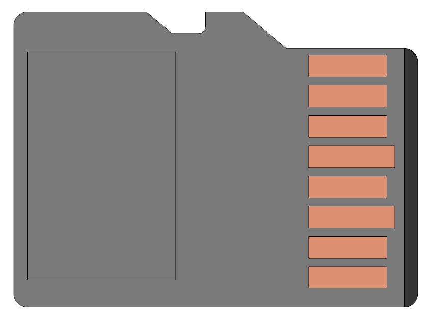
X9 - MicroSD slot
-
It is not primarily recommended to use the microSD slot in devices where significant vibrations are expected. SD card is not included with the "RI" version of servoamplifiers. For more information, see SD cards.
-
X10 - CAN
-
Molex ClikMate 5031490800 - recommended crimping contacts Molex 502579 3
pin # Marking Description 1 CAN-H signal CANH (High) isolated 2 CAN-L signal CANL (Low) isolated 3 CAN GND Iso GND for CAN 4 CAN GND Iso GND for CAN 5 CAN-H signal CANH (High) isolated 6 CAN-L signal CANL (Low) isolated 7 CAN TERM-H termination short input TERM-L – CAN termination 8 CAN TERM-L termination short input TERM-H – CAN termination -
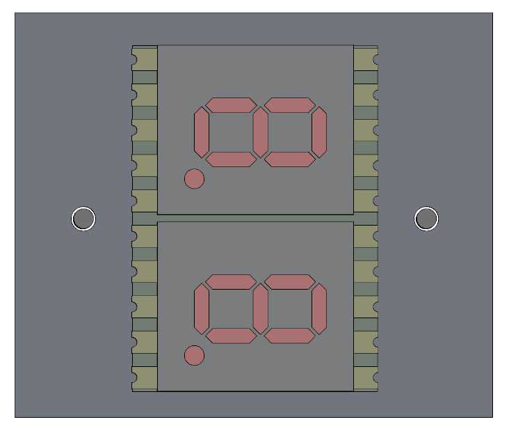
LED display
-
LED display indicates the status of the servoamplifier. See TGZ status indicators for detailed description.
-
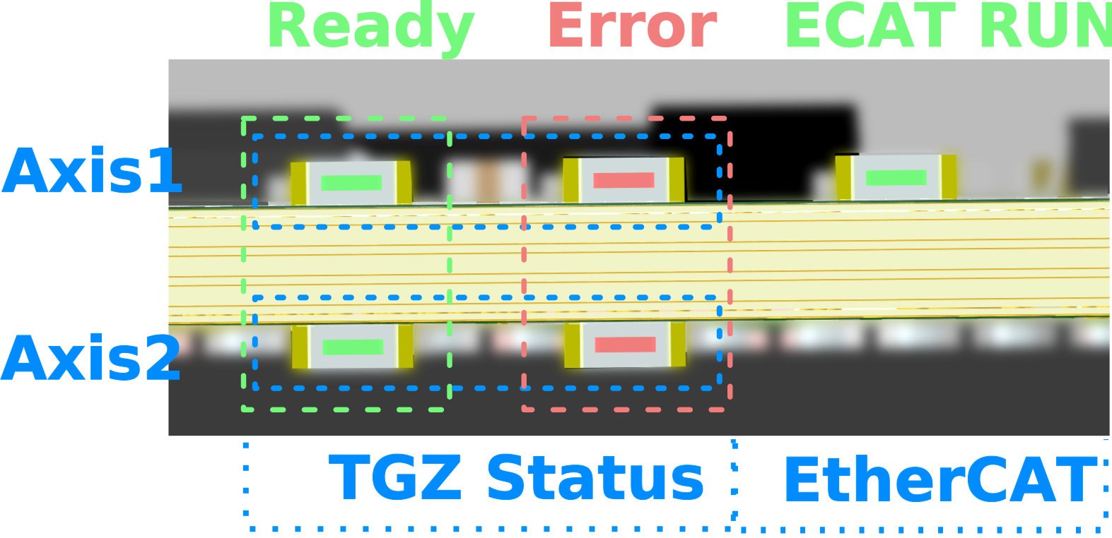
status LEDs
-
LED diodes
LED color Status green Servo OK red Servo Error A complete description of the meaning of the status LEDs can be found here: TGZ status indicators
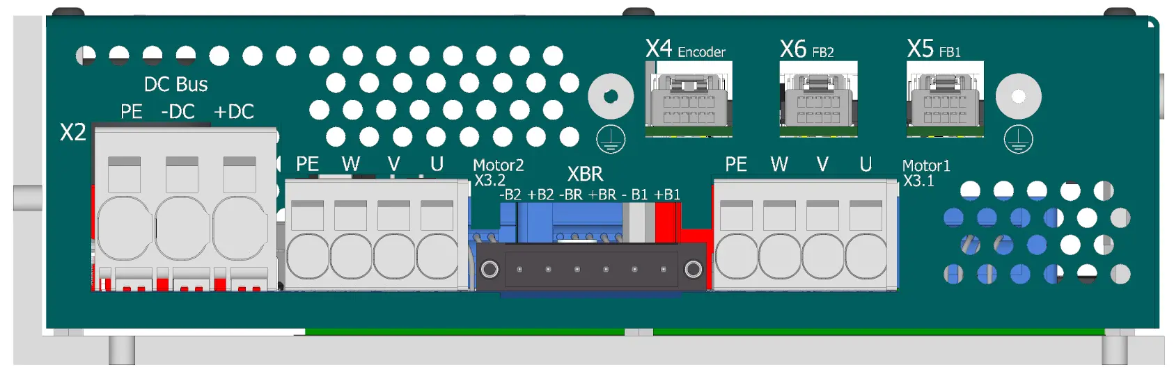
Feedback/motor side view
-
X4 - External encoder (FBE)
-
Molex ClikMate 5031491200 - recommended crimping contacts Molex 502579 3
pin # Endat 2.2/SSI/BISS Hiperface DSL Incremental encoder RS422, RS485 1 +12 V DSL+ +12 V - 2 GND DSL- GND - 3 MA+ (CLK+) - B+ TxD+/RxD+ 4 MA- (CLK-) - B- TxD-/RxD- 5 SLO+ (DATA+) FBSEL+ A+ TxD+/RxD+ 6 SLO- (DATA-) FBSEL- A- TxD-/RxD- 7 - FBSEL+ - - 8 - FBSEL- - - 9 ZERO+ - Z+ RxD+ 10 ZERO- - Z- RxD- 11 +5V +5V +5V +5V 12 GND GND GND GND For more information on external feedback, see FBE Feedback.
-
X5 - Feedback axis 1
-
Molex ClikMate 5031491000 - recommended crimping contacts Molex 502579 3
pin # Endat 2.2/SSI/BISS Hiperface DSL Incremental encoder RS422, RS485 Hengstler Acuro 1 +12 V DSL+ +12 V +12 V UB+ 2 GND DSL- GND GND UB- 3 MA+ (CLK+) - B+ TxD+/RxD+ - 4 MA- (CLK-) - B- TxD-/RxD- - 5 SLO+ (DATA+) FBSEL+ A+ TxD+/RxD+ DATA+ 6 SLO- (DATA-) FBSEL- A- TxD-/RxD- DATA- 7 - FBSEL+ - - - 8 - FBSEL- - - - 9 +5V +5V +5V +5V - 10 GND GND GND GND - For more information regarding Feedback 1, please see Feedback FB1, FB2.
Warning
In order to use Hiperface DSL feedback user must tie pins 5-7 and 6-8 together of the FB1 (and FB2 respectively) connector or assembly appropriate shorting resistors to the control PCB. Also check whether you have correct firmware uploaded in the device.
-
X6 - Feedback axis 2
-
Molex ClikMate 5031491000 - recommended crimping contacts Molex 502579 3
pin # Endat 2.2/SSI/BISS Hiperface DSL Incremental encoder RS422, RS485 Hengstler ACURO link 1 +12 V DSL+ +12 V +12 V UB+ 2 GND DSL- GND GND UB- 3 MA+ (CLK+) - B+ TxD+/RxD+ - 4 MA- (CLK-) - B- TxD-/RxD- - 5 SLO+ (DATA+) FBSEL+ A+ TxD+/RxD+ DATA+ 6 SLO- (DATA-) FBSEL- A- TxD-/RxD- DATA- 7 - FBSEL+ - - - 8 - FBSEL- - - - 9 +5V +5V +5V +5V - 10 GND GND GND GND - For more information regarding Feedback 1, please see Feedback FB1, FB2.
Warning
In order to use Hiperface DSL feedback user must tie pins 5-7 and 6-8 together of the FB1 (and FB2 respectively) connector or assembly appropriate shorting resistors to the control PCB. Also check whether you have correct firmware uploaded in the device.
-
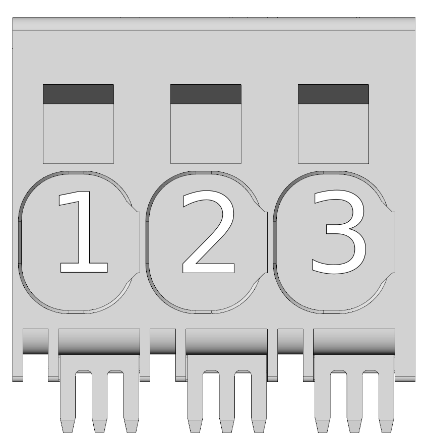
X2 - Power supply voltage (DC bus)
-
Wago push-in CAGE CLAMP®
pin # Marking Description AWG 1 PE protect earth 5-18 2 -DC 0 V 5-18 3 +DC 0 ~ +48VDC 5-18 Max. AWG
Maximum wire cross section possible can be up to 4 AWG when using fine stranded wire without a ferrule.
Regenerative braking
In cases when the drive is not powered by a battery (e.g., a Li-ion battery pack), it is necessary for machines with greater kinetic energy to ensure its dissipation, for example, in a resistive element using a chopper unit.
-
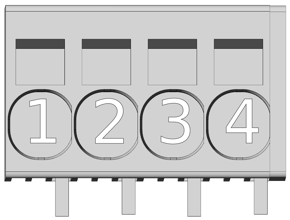
X3.1 - Motor connector - axis 1
-
Wago push-in CAGE CLAMP®
pin # Marking Description AWG 1 PE protect earth 10-24 2 W Phase W 10-24 3 V Phase V 10-24 4 U Phase U 10-24 Max. AWG
Maximum wire cross section possible can be up to 8 AWG when using fine stranded wire without a ferrule.
-
X3.2 - Motor connector - axis 2
-
Wago push-in CAGE CLAMP®
pin # Marking Description AWG 1 PE protect earth 10-24 2 W Phase W 10-24 3 V Phase V 10-24 4 U Phase U 10-24 Max. AWG
Maximum wire cross section possible can be up to 8 AWG when using fine stranded wire without a ferrule.
-
XBR - Static brake connector - axis 1 and 2
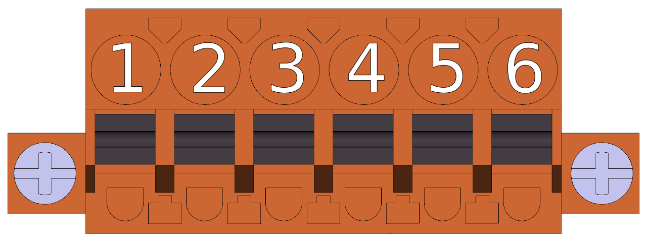
Holding motor brake
For additional information on using the motor brake with the TGZ servo drive, see the Standard Brake section.
-
Weidmüller BLF 5.00HC/06/180F SN OR BX
pin # Marking Description AWG 1 -B2 - Brake motor 2 13-26 2 +B2 + Brake motor 2 13-26 3 -BR – Brake power 13-26 4 +BR + Brake power 13-26 5 -B1 - Brake motor 1 13-26 6 +B1 + Brake motor 1 13-26
-
These types work with modified firmware. It is recommended to always consult with manufacturer about their use. ↩↩
-
Hall sensors must be connected to the digital inputs using a special level shifter. For more information see. Hall converter. ↩↩↩
-
When crimping and connecting the Molex Clik-Mate connectors, follow the Molex Clik-Mate Application Guide and use the recommended crimping tool 2002187400 ↩↩↩↩↩↩↩↩↩↩↩