Parameter settings
Parameter settings
The settings of all parameters of the TGZ servo amplifier are available in the Parameters tab. In addition to this detailed setting, it is also possible to find detailed information about the connected servo amplifier (type, serial number, etc.).
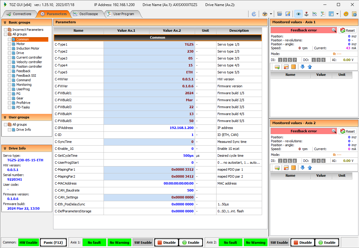
The open window also consists of several panes:
- BASIC GROUPS - list of parameter groups (in individual groups it is possible to find and set all parameters of the servo amplifier).
- USER GROUPS - user groups (allow setting the display of selected parameter groups).
- DRIVE INFO - displays information about the given servo amplifier (type, serial number, HW version, firmware version, etc.).
- PARAMETERS - display and edit parameters of the active group
- MONITORED VALUES - AXIS 1 - displays basic status information (position, speed, proud, etc.) of Axis 1 of the TGZ servo amplifier, displays a code of possible errors and allows its reset.
- MONITORED VALUES - AXIS 2 - displays basic status information (position, speed, proud, etc.) of Axis 2 of the TGZ servo amplifier, displays a code of possible errors and allows its reset.
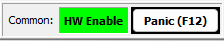
At the bottom of the window there is an informative status bar with several function buttons:
-
COMMON
-
HW ENABLE status information the Disable function key allows the HW ENABLE to be switched off simultaneously on both axes of the servo amplifier
-
AXIS 1

-
- display of information about the status of axis 1 (error, warning message SW Enable)
- the function key Disable enables switching off the SW ENABLE for axis 1
- the function key Enable allows to switch on SW ENABLE for axis 1
-
AXIS 2

-
- display of information about the status of axis 2 (error, warning message SW Enable)
- the function key Disable enables switching off the SW ENABLE for axis 2
- the function key Enable allows to switch on SW ENABLE for axis 2
Basic TGZ parameters in the TGZ GUI
| Description of TGZ main parameters | |||||||||
| Name | Axis | Basic Group | Index (ETH) | Group Index |
Item Index |
Access | Unit | Size | Description [EN] |
| C-Type1 | Common | 0x2000 | 0 | 0 | read-only | chars | 32 bits | Servo drive hw type 1/5 | |
| C-Type2 | Common | 0x2001 | 0 | 1 | read-only | chars | 32 bits | Servo drive hw type 2/5 | |
| C-Type3 | Common | 0x2002 | 0 | 2 | read-only | chars | 32 bits | Servo drive hw type 3/5 | |
| C-Type4 | Common | 0x2003 | 0 | 3 | read-only | chars | 32 bits | Servo drive hw type 4/5 | |
| C-Type5 | Common | 0x2004 | 0 | 4 | read-only | chars | 32 bits | Servo drive hw type 5/5 | |
| C-HWVer | Common | 0x2005 | 0 | 5 | read-only | chars | 32 bits | HW version | |
| C-FWVer | Common | 0x2006 | 0 | 6 | read-only | chars | 32 bits | Firmware version | |
| C-FWBuild1 | Common | 0x2007 | 0 | 7 | read-only | chars | 32 bits | Firmware build 1/5 | |
| C-FWBuild2 | Common | 0x2008 | 0 | 8 | read-only | chars | 32 bits | Firmware build 2/5 | |
| C-FWBuild3 | Common | 0x2009 | 0 | 9 | read-only | chars | 32 bits | Firmware build 3/5 | |
| C-FWBuild4 | Common | 0x200A | 0 | 10 | read-only | chars | 32 bits | Firmware build 4/5 | |
| C-FWBuild5 | Common | 0x200B | 0 | 11 | read-only | chars | 32 bits | Firmware build 5/5 | |
| C-IPAddress | Common | 0x200C | 0 | 12 | read-write | - | 32 bits | IP address X11 service UDP chanel | |
| C-ID | Common | 0x200D | 0 | 13 | read-write | - | 32 bits | ID fieldbus | |
| C-SyncTime | Common | 0x200E | 0 | 14 | read-only | - | 32 bits | Measured time between synchronization pulses (only for DC functionality) |
|
| C-Enable_1G | Common | 0x200F | 0 | 15 | read-write | - | 32 bits | Enable 1G speed fieldbus (preparing) | |
| C-SetCycleTime | Common | 0x2010 | 0 | 16 | read-write | us | 32 bits | Desired cycle time (used only without DC functionality) |
|
| C-UserProgStart | Common | 0x2011 | 0 | 17 | read-write | - | 32 bits | Enable autostart of user program : 0 .. no autostart, 1 .. autostart from flash memory, (2 .. autostart from SD .. preparing) |
|
| M-Name1 | Axis 1 | Motor | 0x2100 | 1 | 0 | read-write | chars | 32 bits | Motor name 1 1/6 |
| M-Name1 | Axis 2 | Motor | 0x2200 | 2 | 0 | read-write | chars | 32 bits | Motor name 2 1/6 |
| M-Name2 | Axis 1 | Motor | 0x2101 | 1 | 1 | read-write | chars | 32 bits | Motor name 1 2/6 |
| M-Name2 | Axis 2 | Motor | 0x2201 | 2 | 1 | read-write | chars | 32 bits | Motor name 2 2/6 |
| M-Name3 | Axis 1 | Motor | 0x2102 | 1 | 2 | read-write | chars | 32 bits | Motor name 1 3/6 |
| M-Name3 | Axis 2 | Motor | 0x2202 | 2 | 2 | read-write | chars | 32 bits | Motor name 2 3/6 |
| M-Name4 | Axis 1 | Motor | 0x2103 | 1 | 3 | read-write | chars | 32 bits | Motor name 1 4/6 |
| M-Name4 | Axis 2 | Motor | 0x2203 | 2 | 3 | read-write | chars | 32 bits | Motor name 2 4/6 |
| M-Name5 | Axis 1 | Motor | 0x2104 | 1 | 4 | read-write | chars | 32 bits | Motor name 1 5/6 |
| M-Name5 | Axis 2 | Motor | 0x2204 | 2 | 4 | read-write | chars | 32 bits | Motor name 2 5/6 |
| M-Name6 | Axis 1 | Motor | 0x2105 | 1 | 5 | read-write | chars | 32 bits | Motor name 1 6/6 |
| M-Name6 | Axis 2 | Motor | 0x2205 | 2 | 5 | read-write | chars | 32 bits | Motor name 2 6/6 |
| M-Inull | Axis 1 | Motor | 0x2106 | 1 | 6 | read-write | mA(rms) | 32 bits | Allowed stall rms current of motor 1 |
| M-Inull | Axis 2 | Motor | 0x2206 | 2 | 6 | read-write | mA(rms) | 32 bits | Allowed stall rms current of motor 2 |
| M-Ipeak | Axis 1 | Motor | 0x2107 | 1 | 7 | read-write | mA | 32 bits | Allowed peak current amplitude of motor 1 (Iamp = 1.41 * Irms) |
| M-Ipeak | Axis 2 | Motor | 0x2207 | 2 | 7 | read-write | mA | 32 bits | Allowed peak current amplitude of motor 2 (Iamp = 1.41 * Irms) |
| M-Nmax | Axis 1 | Motor | 0x2108 | 1 | 8 | read-write | rpm | 32 bits | Maximal mechanical speed of motor 1 - error limit |
| M-Nmax | Axis 2 | Motor | 0x2208 | 2 | 8 | read-write | rpm | 32 bits | Maximal mechanical speed of motor 2 - error limit |
| M-Polepairs | Axis 1 | Motor | 0x2109 | 1 | 9 | read-write | - | 32 bits | Number of motor 1 polepairs (polepairs = poles / 2) |
| M-Polepairs | Axis 2 | Motor | 0x2209 | 2 | 9 | read-write | - | 32 bits | Number of motor 2 polepairs (polepairs = poles / 2) |
| M-CommutOffset | Axis 1 | Motor | 0x210A | 1 | 10 | read-write | - | 32 bits | Angle offset between zero of feedback encoder and stator of motor 1 |
| M-CommutOffset | Axis 2 | Motor | 0x220A | 2 | 10 | read-write | - | 32 bits | Angle offset between zero of feedback encoder and stator of motor 2 |
| M-MinResTerm | Axis 1 | Motor | 0x210B | 1 | 11 | read-write | Ohm | 32 bits | Limit for overtemperature error - Minimal resistivity of motor 1 thermal sensor (used only for digital feedback with connected thermal sensor) |
| M-MinResTerm | Axis 2 | Motor | 0x220B | 2 | 11 | read-write | Ohm | 32 bits | Limit for overtemperature error - Minimal resistivity of motor 2 thermal sensor (used only for digital feedback with connected thermal sensor) |
| M-MaxResTerm | Axis 1 | Motor | 0x210C | 1 | 12 | read-write | Ohm | 32 bits | Limit for overtemperature error - Maximal resistivity of motor 1 thermal sensor (used only for digital feedback with connected thermal sensor) |
| M-MaxResTerm | Axis 2 | Motor | 0x220C | 2 | 12 | read-write | Ohm | 32 bits | Limit for overtemperature error - Maximal resistivity of motor 2 thermal sensor (used only for digital feedback with connected thermal sensor) |
| M-StaticBrake | Axis 1 | Motor | 0x210D | 1 | 13 | read-write | - | 32 bits | Motor 1 static brake: 1 = yes , 0 = no |
| M-StaticBrake | Axis 2 | Motor | 0x220D | 2 | 13 | read-write | - | 32 bits | Motor 2 static brake: 1 = yes , 0 = no |
| M-ThermTimeConst | Axis 1 | Motor | 0x210E | 1 | 14 | read-write | s | 32 bits | ThermalTimeConstant of motor 1 |
| M-ThermTimeConst | Axis 2 | Motor | 0x220E | 2 | 14 | read-write | s | 32 bits | ThermalTimeConstant of motor 2 |
| D-Name1 | Axis 1 | Drive | 0x2300 | 3 | 0 | read-write | chars | 32 bits | Drive 1 name 1/3 |
| D-Name1 | Axis 2 | Drive | 0x2400 | 4 | 0 | read-write | chars | 32 bits | Drive 2 name 1/3 |
| D-Name2 | Axis 1 | Drive | 0x2301 | 3 | 1 | read-write | chars | 32 bits | Drive 1 name 2/3 |
| D-Name2 | Axis 2 | Drive | 0x2401 | 4 | 1 | read-write | chars | 32 bits | Drive 2 name 2/3 |
| D-Name3 | Axis 1 | Drive | 0x2302 | 3 | 2 | read-write | chars | 32 bits | Drive 1 name 3/3 |
| D-Name3 | Axis 2 | Drive | 0x2402 | 4 | 2 | read-write | chars | 32 bits | Drive 2 name 3/3 |
| D-Mode | Axis 1 | Drive | 0x2303 | 3 | 3 | read-write | - | 32 bits | Mode of drive 1 - see manual |
| D-Mode | Axis 2 | Drive | 0x2403 | 4 | 3 | read-write | - | 32 bits | Mode of drive 2 - see manual |
| D-DelayEnable_Hwen | Axis 1 | Drive | 0x230A | 3 | 10 | read-write | 0.1ms | 32 bits | Delay enable drive 1 after HW enable signal rising edge X1 |
| D-DelayEnable_Hwen | Axis 2 | Drive | 0x240A | 4 | 10 | read-write | 0.1ms | 32 bits | Delay enable drive 2 after HW enable signal rising edge X1 |
| D-DelayUnbrake_Enable | Axis 1 | Drive | 0x230B | 3 | 11 | read-write | 0.1ms | 32 bits | Delay release brake of motor 1 after enable drive |
| D-DelayUnbrake_Enable | Axis 2 | Drive | 0x240B | 4 | 11 | read-write | 0.1ms | 32 bits | Delay release brake of motor 2 after enable drive |
| D-DelayDisable_Brake | Axis 1 | Drive | 0x230C | 3 | 12 | read-write | 0.1ms | 32 bits | Delay disable drive 1 after activating brake |
| D-DelayDisable_Brake | Axis 2 | Drive | 0x240C | 4 | 12 | read-write | 0.1ms | 32 bits | Delay disable drive 2 after activating brake |
| D-VoltDCLinkMinErrLim | Drive | 0x230D | 3 | 13 | read-write | V | 32 bits | Minimal DC link voltage - low voltage error level | |
| D-VoltDCLinkMaxErrLim | Drive | 0x230E | 3 | 14 | read-write | V | 32 bits | Maximal DC link voltage - high voltage error level |
|
| C-K | Axis 1 | Currentcontroller | 0x2500 | 5 | 0 | read-write | mV/A | 32 bits | Current controller Q gain |
| C-K | Axis 2 | Currentcontroller | 0x2600 | 6 | 0 | read-write | mV/A | 32 bits | Current controller Q gain |
| C-Ti | Axis 1 | Currentcontroller | 0x2501 | 5 | 1 | read-write | µs | 32 bits | Current controller integral time |
| C-Ti | Axis 2 | Currentcontroller | 0x2601 | 6 | 1 | read-write | µs | 32 bits | Current controller integral time |
| C-KDr | Axis 1 | Currentcontroller | 0x2502 | 5 | 2 | read-write | % | 32 bits | Current controller D relative gain to K |
| C-KDr | Axis 2 | Currentcontroller | 0x2602 | 6 | 2 | read-write | % | 32 bits | Current controller D relative gain to K |
| C-Tc | Axis 1 | Currentcontroller | 0x2503 | 5 | 3 | read-write | µs | 32 bits | Time constant of current command filter (not used) |
| C-Tc | Axis 2 | Currentcontroller | 0x2603 | 6 | 3 | read-write | µs | 32 bits | Time constant of current command filter (not used) |
| C-Filt | Axis 1 | Currentcontroller | 0x2504 | 5 | 4 | read-write | % | 32 bits | Percentable value of current command (100 = 100% goes via filter) (not used) |
| C-Filt | Axis 2 | Currentcontroller | 0x2604 | 6 | 4 | read-write | % | 32 bits | Percentable value of current command (100 = 100% goes via filter) (not used) |
| C-LimN | Axis 1 | Currentcontroller | 0x2505 | 5 | 5 | read-write | 0,1% | 32 bits | Current amplitude negative limit relatively to M- Inull (limiting output of speed controller) |
| C-LimN | Axis 2 | Currentcontroller | 0x2605 | 6 | 5 | read-write | 0,1% | 32 bits | Current amplitude negative limit relatively to M- Inull (limiting output of speed controller) |
| C-LimP | Axis 1 | Currentcontroller | 0x2506 | 5 | 6 | read-write | 0,1% | 32 bits | Current amplitude positive limit relatively to M- Inull (limiting output of speed controller) |
| C-LimP | Axis 2 | Currentcontroller | 0x2606 | 6 | 6 | read-write | 0,1% | 32 bits | Current amplitude positive limit relatively to M- Inull (limiting output of speed controller) |
| C-VoltLimMin | Axis 1 | Currentcontroller | 0x2507 | 5 | 7 | read-write | % | 32 bits | Negative voltage limit (output of current controller) |
| C-VoltLimMin | Axis 2 | Currentcontroller | 0x2607 | 6 | 7 | read-write | % | 32 bits | Negative voltage limit (output of current controller) |
| C-VoltLimMax | Axis 1 | Currentcontroller | 0x2508 | 5 | 8 | read-write | % | 32 bits | Possitive voltage limit (output of current controller) |
| C-VoltLimMax | Axis 2 | Currentcontroller | 0x2608 | 6 | 8 | read-write | % | 32 bits | Possitive voltage limit (output of current controller) |
| C-CogCompFac | Axis 1 | Currentcontroller | 0x2509 | 5 | 9 | read-write | % | 32 bits | Cogging compensation factor 0 .. Off (Before using function must be measured compensation data of motor) |
| C-CogCompFac | Axis 2 | Currentcontroller | 0x2609 | 6 | 9 | read-write | % | 32 bits | Cogging compensation factor 0 .. Off (Before using function must be measured compensation data of motor) |
| V-K | Axis 1 | Velocitycontroller | 0x2700 | 7 | 0 | read-write | mA/1000rpm | 32 bits | Velocity controller gain |
| V-K | Axis 2 | Velocitycontroller | 0x2800 | 8 | 0 | read-write | mA/1000rpm | 32 bits | Velocity controller gain |
| V-Ti | Axis 1 | Velocitycontroller | 0x2701 | 7 | 1 | read-write | µs | 32 bits | Velocity controller integral time |
| V-Ti | Axis 2 | Velocitycontroller | 0x2801 | 8 | 1 | read-write | µs | 32 bits | Velocity controller integral time |
| V-LimN | Axis 1 | Velocitycontroller | 0x2702 | 7 | 2 | read-write | rpm | 32 bits | Velocity negative limit (limiting output of position controller) |
| V-LimN | Axis 2 | Velocitycontroller | 0x2802 | 8 | 2 | read-write | rpm | 32 bits | Velocity negative limit (limiting output of position controller) |
| V-LimP | Axis 1 | Velocitycontroller | 0x2703 | 7 | 3 | read-write | rpm | 32 bits | Velocity positive limit (limiting output of position controller) |
| V-LimP | Axis 2 | Velocitycontroller | 0x2803 | 8 | 3 | read-write | rpm | 32 bits | Velocity positive limit (limiting output of position controller) |
| V-Tfb | Axis 1 | Velocitycontroller | 0x2704 | 7 | 4 | read-write | µs | 32 bits | Time constant of velocity feedback lowpass filter (not used) |
| V-Tfb | Axis 2 | Velocitycontroller | 0x2804 | 8 | 4 | read-write | µs | 32 bits | Time constant of velocity feedback lowpass filter (not used) |
| V-Tv | Axis 1 | Velocitycontroller | 0x2705 | 7 | 5 | read-write | µs | 32 bits | Time constant of velocity command lowpass filter (not used) |
| V-Tv | Axis 2 | Velocitycontroller | 0x2805 | 8 | 5 | read-write | µs | 32 bits | Time constant of velocity command lowpass filter (not used) |
| V-FiFact | Axis 1 | Velocitycontroller | 0x2706 | 7 | 6 | read-write | 0,1% | 32 bits | Velocity filter factor 0 .. not filtered (not used) |
| V-FiFact | Axis 2 | Velocitycontroller | 0x2806 | 8 | 6 | read-write | 0,1% | 32 bits | Velocity filter factor 0 .. not filtered (not used) |
| P-K | Axis 1 | Positioncontroller | 0x2900 | 9 | 0 | read-write | 0.001 1/s | 32 bits | Position controller gain |
| P-K | Axis 2 | Positioncontroller | 0x2A00 | 10 | 0 | read-write | 0.001 1/s | 32 bits | Position controller gain |
| P-SFF | Axis 1 | Positioncontroller | 0x2901 | 9 | 1 | read-write | 0,1% | 32 bits | Speed feed forward |
| P-SFF | Axis 2 | Positioncontroller | 0x2A01 | 10 | 1 | read-write | 0,1% | 32 bits | Speed feed forward |
| P-MaxAngleError | Axis 1 | Positioncontroller | 0x2902 | 9 | 2 | read-write | --- | 32 bits | maximal position error - angle part |
| P-MaxAngleError | Axis 2 | Positioncontroller | 0x2A02 | 10 | 2 | read-write | --- | 32 bits | maximal position error - angle part |
| P-MaxRevolError | Axis 1 | Positioncontroller | 0x2903 | 9 | 3 | read-write | --- | 32 bits | maximal position error - revolution part |
| P-MaxRevolError | Axis 2 | Positioncontroller | 0x2A03 | 10 | 3 | read-write | --- | 32 bits | maximal position error - revolution part |
| F-Type | Axis 1 | Feedback | 0x2B00 | 11 | 0 | read-write | - | 32 bits | Feedback type : 1.. Hiperface DSL, 2.. Endat , 4.. Incremental, 6.. BISS, 7.. SSI |
| F-Type | Axis 2 | Feedback | 0x2C00 | 12 | 0 | read-write | - | 32 bits | Feedback type : 1.. Hiperface DSL, 2.. Endat , 4.. Incremental, 6.. BISS, 7.. SSI |
| F-Resolution | Axis 1 | Feedback | 0x2B01 | 11 | 1 | read-write | - | 32 bits | Feedback resolution per revolution(read only for digital feedbacks type 1 and 2) |
| F-Resolution | Axis 2 | Feedback | 0x2C01 | 12 | 1 | read-write | - | 32 bits | Feedback resolution per revolution(read only for digital feedbacks type 1 and 2) |
| F-IncrEnc | Axis 1 | Feedback | 0x2B02 | 11 | 2 | read-write | pulses | 32 bits | Incremental encoder feedback resolution |
| F-IncrEnc | Axis 2 | Feedback | 0x2C02 | 12 | 2 | read-write | pulses | 32 bits | Incremental encoder feedback resolution |
| F-ExtIncrEnc | Feedback | 0x2B03 | 11 | 3 | read-write | pulses | 32 bits | External incremental encoder resolution | |
| F-ResolverPoles | Axis 1 | Feedback | 0x2B04 | 11 | 4 | read-write | - | 32 bits | Number of resolver poles (not used - only for optional board) |
| F-ResolverPoles | Axis 2 | Feedback | 0x2C04 | 12 | 4 | read-write | - | 32 bits | Number of resolver poles (not used - only for optional board) |
| K-Command | Axis 1 | Command | 0x3100 | 17 | 0 | read-write | - | 32 bits | Command bits[1,0]=01 .. SW enable bit[3] = 1 .. Clear errors |
| K-Command | Axis 2 | Command | 0x3200 | 18 | 0 | read-write | - | 32 bits | Command bits[1,0]=01 .. SW enable bit[3] = 1 .. Clear errors |
| K-I | Axis 1 | Command | 0x3101 | 17 | 1 | read-write | mA | 32 bits | Required current (current mode = 1) |
| K-I | Axis 2 | Command | 0x3201 | 18 | 1 | read-write | mA | 32 bits | Required current (current mode = 1) |
| K-V | Axis 1 | Command | 0x3102 | 17 | 2 | read-write | rpm | 32 bits | Required velocity (velocity mode = 2) |
| K-V | Axis 2 | Command | 0x3202 | 18 | 2 | read-write | rpm | 32 bits | Required velocity (velocity mode = 2) |
| K-P_Angle | Axis 1 | Command | 0x3103 | 17 | 3 | read-write | - | 32 bits | Required position - angle (position mode = 3) |
| K-P_Angle | Axis 2 | Command | 0x3203 | 18 | 3 | read-write | - | 32 bits | Required position - angle (position mode = 3) |
| K-P_Revol | Axis 1 | Command | 0x3104 | 17 | 4 | read-write | - | 32 bits | Required position - revolutions (position mode = 3) |
| K-P_Revol | Axis 2 | Command | 0x3204 | 18 | 4 | read-write | - | 32 bits | Required position - revolutions (position mode = 3) |
| K-DigitalOutputForce_Set | Axis 1 | Command | 0x3109 | 17 | 9 | read-write | - | 32 bits | force outputs - set |
| K-DigitalOutputForce_Set | Axis 2 | Command | 0x3209 | 18 | 9 | read-write | - | 32 bits | force outputs - set |
| K-DigitalOutputForce_Clr | Axis 1 | Command | 0x310A | 17 | 10 | read-write | - | 32 bits | force outputs - clear |
| K-DigitalOutputForce_Clr | Axis 2 | Command | 0x320A | 18 | 10 | read-write | - | 32 bits | force outputs - clear |
| Monitor-Counter | Monitoring | 0x3300 | 19 | 0 | read-only | - | 32 bits | Main counter | |
| aIa | Axis 1 | Monitoring | 0x3301 | 19 | 1 | read-only | mA | 32 bits | Actual current phase A |
| aIa | Axis 2 | Monitoring | 0x3401 | 20 | 1 | read-only | mA | 32 bits | Actual current phase A |
| aIb | Axis 1 | Monitoring | 0x3302 | 19 | 2 | read-only | mA | 32 bits | Actual current phase B |
| aIb | Axis 2 | Monitoring | 0x3402 | 20 | 2 | read-only | mA | 32 bits | Actual current phase B |
| aIc | Axis 1 | Monitoring | 0x3303 | 19 | 3 | read-only | mA | 32 bits | Actual current phase C |
| aIc | Axis 2 | Monitoring | 0x3403 | 20 | 3 | read-only | mA | 32 bits | Actual current phase C |
| aIq | Axis 1 | Monitoring | 0x3306 | 19 | 6 | read-only | mA | 32 bits | Actual current q |
| aIq | Axis 2 | Monitoring | 0x3406 | 20 | 6 | read-only | mA | 32 bits | Actual current q |
| aId | Axis 1 | Monitoring | 0x3307 | 19 | 7 | read-only | mA | 32 bits | Actual current d |
| aId | Axis 2 | Monitoring | 0x3407 | 20 | 7 | read-only | mA | 32 bits | Actual current d |
| aAngle | Axis 1 | Monitoring | 0x3310 | 19 | 16 | read-only | inc | 32 bits | Actual position per revolution (resolution : 32bit per revolution) |
| aAngle | Axis 2 | Monitoring | 0x3410 | 20 | 16 | read-only | inc | 32 bits | Actual position per revolution (resolution : 32bit per revolution) |
| aRevol | Axis 1 | Monitoring | 0x3311 | 19 | 17 | read-only | 1 | 32 bits | Actual number of revolutions |
| aRevol | Axis 2 | Monitoring | 0x3411 | 20 | 17 | read-only | 1 | 32 bits | Actual number of revolutions |
| aSpeed | Axis 1 | Monitoring | 0x3312 | 19 | 18 | read-only | rpm | 32 bits | Actual motor speed |
| aSpeed | Axis 2 | Monitoring | 0x3412 | 20 | 18 | read-only | rpm | 32 bits | Actual motor speed |
| aSpeedError | Axis 1 | Monitoring | 0x3314 | 19 | 20 | read-only | rpm | 32 bits | Actual speed error |
| aSpeedError | Axis 2 | Monitoring | 0x3414 | 20 | 20 | read-only | rpm | 32 bits | Actual speed error |
| aAngleError | Axis 1 | Monitoring | 0x331C | 19 | 28 | read-only | rpm | 32 bits | Actual angle error |
| aAngleError | Axis 2 | Monitoring | 0x341C | 20 | 28 | read-only | rpm | 32 bits | Actual angle error |
| aRevolError | Axis 1 | Monitoring | 0x331D | 19 | 29 | read-only | rpm | 32 bits | Actual revol error |
| aRevolError | Axis 2 | Monitoring | 0x341D | 20 | 29 | read-only | rpm | 32 bits | Actual revol error |
| aDriveStatus | Axis 1 | Monitoring | 0x3325 | 19 | 37 | read-only | -- | 32 bits | Status of drive : bit[0] = 1 .. Enabled, bit[1] = 1 .. HW Enable signal, bit[2] = 1 .. Software enable, bit[3] = 1 .. Brake released, bit [4] = 1 .. No error, bit[5] = 1 .. Initialization finished, bit[6] = 1 ..fieldbus mode, ............. |
| aDriveStatus | Axis 2 | Monitoring | 0x3425 | 20 | 37 | read-only | -- | 32 bits | Status of drive : bit[0] = 1 .. Enabled, bit[1] = 1 .. HW Enable signal, bit[2] = 1 .. Software enable, bit[3] = 1 .. Brake released, bit [4] = 1 .. No error, bit[5] = 1 .. Initialization finished, bit[6] = 1 ..fieldbus mode, .............. |
| aDriveError | Axis 1 | Monitoring | 0x3326 | 19 | 38 | read-only | -- | 32 bits | Error of drive (see manual) |
| aDriveError | Axis 2 | Monitoring | 0x3426 | 20 | 38 | read-only | -- | 32 bits | Error of drive (see manual) |
| aDriveWarning | Axis 1 | Monitoring | 0x3327 | 19 | 39 | read-only | -- | 32 bits | Warning (not used) |
| aDriveWarning | Axis 2 | Monitoring | 0x3427 | 20 | 39 | read-only | -- | 32 bits | Warning (not used) |
| AnInput | Axis 1 | Monitoring | 0x3328 | 19 | 40 | read-only | 0,1% | 32 bits | Analogue input 1 |
| AnInput | Axis 2 | Monitoring | 0x3428 | 20 | 40 | read-only | 0,1% | 32 bits | Analogue input 2 |
| VoltDCLink | Monitoring | 0x3329 | 19 | 41 | read-only | V | 32 bits | DC-link voltage | |
| OnChipTemp | Monitoring | 0x332A | 19 | 42 | read-only | deg | 32 bits | CPU temperature | |
| ec_SetPointAngle | Axis 1 | Monitoring | 0x332B | 19 | 43 | read-only | inc | 32 bits | Desired position per revolution (fieldbus) |
| ec_SetPointAngle | Axis 2 | Monitoring | 0x342B | 20 | 43 | read-only | inc | 32 bits | Desired position per revolution (fieldbus) |
| ec_SetPointRevol | Axis 1 | Monitoring | 0x332C | 19 | 44 | read-only | 1 | 32 bits | Desired number of revolutions (fieldbus) |
| ec_SetPointRevol | Axis 2 | Monitoring | 0x342C | 20 | 44 | read-only | 1 | 32 bits | Desired number of revolutions (fieldbus) |
| ec_control | Axis 1 | Monitoring | 0x332D | 19 | 45 | read-only | 1 | 32 bits | Fieldbus control register |
| ec_control | Axis 2 | Monitoring | 0x342D | 20 | 45 | read-only | 1 | 32 bits | Fieldbus control register |
| ec_currentSetPoint | Axis 1 | Monitoring | 0x332E | 19 | 46 | read-only | 1 | 32 bits | Fieldbus current setpoint |
| ec_currentSetPoint | Axis 2 | Monitoring | 0x342E | 20 | 46 | read-only | 1 | 32 bits | Fieldbus current setpoint |
| ec_currentLimit | Axis 1 | Monitoring | 0x332F | 19 | 47 | read-only | 1 | 32 bits | Fieldbus current limitation |
| ec_currentLimit | Axis 2 | Monitoring | 0x342F | 20 | 47 | read-only | 1 | 32 bits | Fieldbus current limitation |
| Digital_Inputs | Axis 1 | Monitoring | 0x3330 | 19 | 48 | read-only | - | 32 bits | Digital inputs : bit[0] .. IN1,bit[1] .. IN3,bit[2] .. IN5,bit[3] .. IN7 |
| Digital_Inputs | Axis 2 | Monitoring | 0x3430 | 20 | 48 | read-only | - | 32 bits | Digital inputs : bit[0] .. IN2,bit[1] .. IN4,bit[2] .. IN6,bit[3] .. IN8 |
| Motor_temperature | Axis 1 | Monitoring | 0x3331 | 19 | 49 | read-only | Ohm | 32 bits | Rezistivity of motor temperature sensor (only for digital feedback with connected temperature sensor) |
| Motor_temperature | Axis 2 | Monitoring | 0x3431 | 20 | 49 | read-only | Ohm | 32 bits | Rezistivity of motor temperature sensor (only for digital feedback with connected temperature sensor) |
| rIq | Axis 1 | Monitoring | 0x3332 | 19 | 50 | read-only | mA | 32 bits | Required current (input - current controller) |
| rIq | Axis 2 | Monitoring | 0x3432 | 20 | 50 | read-only | mA | 32 bits | Required current (input - current controller) |
| Ia_rms | Axis 1 | Monitoring | 0x3333 | 19 | 51 | read-only | mA | 32 bits | Current Ia rms value |
| Ia_rms | Axis 2 | Monitoring | 0x3433 | 20 | 51 | read-only | mA | 32 bits | Current Ia rms value |
| Ib_rms | Axis 1 | Monitoring | 0x3334 | 19 | 52 | read-only | mA | 32 bits | Current Ib rms value |
| Ib_rms | Axis 2 | Monitoring | 0x3434 | 20 | 52 | read-only | mA | 32 bits | Current Ib rms value |
| Ic_rms | Axis 1 | Monitoring | 0x3335 | 19 | 53 | read-only | mA | 32 bits | Current Ic rms value |
| Ic_rms | Axis 2 | Monitoring | 0x3435 | 20 | 53 | read-only | mA | 32 bits | Current Ic rms value |
| aI2t | Axis 1 | Monitoring | 0x3337 | 19 | 55 | read-only | mA | 32 bits | Integrated value I2t |
| aI2t | Axis 2 | Monitoring | 0x3437 | 20 | 55 | read-only | mA | 32 bits | Integrated value I2t |
| rAngle | Axis 1 | Monitoring | 0x3338 | 19 | 56 | read-only | inc | 32 bits | Required position per revolution (input - position controller) |
| rAngle | Axis 2 | Monitoring | 0x3438 | 20 | 56 | read-only | inc | 32 bits | Required position per revolution (input - position controller) |
| rRevol | Axis 1 | Monitoring | 0x3339 | 19 | 57 | read-only | 1 | 32 bits | Required number of revolutions (input - position controller) |
| rRevol | Axis 2 | Monitoring | 0x3439 | 20 | 57 | read-only | 1 | 32 bits | Required number of revolutions (input - position controller) |
| rSpeed | Axis 1 | Monitoring | 0x333A | 19 | 58 | read-only | rpm | 32 bits | Required speed (input - speed controller) |
| rSpeed | Axis 2 | Monitoring | 0x343A | 20 | 58 | read-only | rpm | 32 bits | Required speed (input - speed controller) |
| DSL_status | Axis 1 | Monitoring | 0x333B | 19 | 59 | read-only | bit | 32 bits | Status DSL fb encoder |
| DSL_status | Axis 2 | Monitoring | 0x343B | 20 | 59 | read-only | bit | 32 bits | Status DSL fb encoder |
| DO | Axis 1 | Monitoring | 0x333C | 19 | 60 | read-write | bit | 32 bits | Digital outputs: bit[0] .. Out1, bit[1] .. Out3, bit[2] .. Out5 |
| DO | Axis 2 | Monitoring | 0x343C | 20 | 60 | read-write | bit | 32 bits | Digital outputs: bit[0] .. Out2, bit[1] .. Out4, bit[2] .. Out6 |
| C-PackeTime | Monitoring | 0x3340 | 19 | 64 | read-only | - | 32 bits | Measured time between packets for fieldbus mode |
|
| Acc | Axis 1 | PG | 0x3900 | 25 | 0 | read-write | pginc/s2 | 32 bits | Desired acceleration of movement [ inc/s2 ] .. see functional manual |
| Acc | Axis 2 | PG | 0x3A00 | 26 | 0 | read-write | pginc/s2 | 32 bits | Desired acceleration of movement [ inc/s2 ] .. see functional manual |
| Dec | Axis 1 | PG | 0x3901 | 25 | 1 | read-write | pginc/s2 | 32 bits | Desired deceleration of movenent [ inc/s2 ] .. see functional manual |
| Dec | Axis 2 | PG | 0x3A01 | 26 | 1 | read-write | pginc/s2 | 32 bits | Desired deceleration of movenent [ inc/s2 ] .. see functional manual |
| APosAngle | Axis 1 | PG | 0x3902 | 25 | 2 | read-only | inc | 32 bits | Actual position of movenent[ inc ] .. see functional manual |
| APosAngle | Axis 2 | PG | 0x3A02 | 26 | 2 | read-only | inc | 32 bits | Actual position of movenent[ inc ] .. see functional manual |
| APosRevol | Axis 1 | PG | 0x3903 | 25 | 3 | read-only | inc | 32 bits | Actual position of movenent[ inc ] .. see functional manual |
| APosRevol | Axis 2 | PG | 0x3A03 | 26 | 3 | read-only | inc | 32 bits | Actual position of movenent[ inc ] .. see functional manual |
| DPosAngle | Axis 1 | PG | 0x3904 | 25 | 4 | read-write | inc | 32 bits | Destination position of movenent[ inc ] .. see functional manual |
| DPosAngle | Axis 2 | PG | 0x3A04 | 26 | 4 | read-write | inc | 32 bits | Destination position of movenent[ inc ] .. see functional manual |
| DPosRevol | Axis 1 | PG | 0x3905 | 25 | 5 | read-write | inc | 32 bits | Destination position of movenent[ inc ] .. see functional manual |
| DPosRevol | Axis 2 | PG | 0x3A05 | 26 | 5 | read-write | inc | 32 bits | Destination position of movenent[ inc ] .. see functional manual |
| ASpeed | Axis 1 | PG | 0x3906 | 25 | 6 | read-only | pginc/s | 32 bits | Actual speed of movenent[ inc/s ] .. see functional manual |
| ASpeed | Axis 2 | PG | 0x3A06 | 26 | 6 | read-only | pginc/s | 32 bits | Actual speed of movenent[ inc/s ] .. see functional manual |
| PosSpeed | Axis 1 | PG | 0x3907 | 25 | 7 | read-write | pginc/s | 32 bits | Desired speed of movenent in position mode[ inc/s ] .. see functional manual |
| PosSpeed | Axis 2 | PG | 0x3A07 | 26 | 7 | read-write | pginc/s | 32 bits | Desired speed of movenent in position mode[ inc/s ] .. see functional manual |
| Speed | Axis 1 | PG | 0x3908 | 25 | 8 | read-write | pginc/s | 32 bits | Desired speed of movenent in speed mode[ inc/s ] .. see functional manual |
| Speed | Axis 2 | PG | 0x3A08 | 26 | 8 | read-write | pginc/s | 32 bits | Desired speed of movenent in speed mode[ inc/s ] .. see functional manual |
| Mode | Axis 1 | PG | 0x3909 | 25 | 9 | read-write | - | 32 bits | Mode of profile generator 0 = speed mode, 1 = position mode, 2( only read ) = signalizing deceleration ramp in position mode .. see functional manual |
| Mode | Axis 2 | PG | 0x3A09 | 26 | 9 | read-write | - | 32 bits | Mode of profile generator 0 = speed mode, 1 = position mode, 2( only read ) = signalizing deceleration ramp in position mode .. see functional manual |
| Rdy | Axis 1 | PG | 0x390A | 25 | 10 | read-write | - | 32 bits | Flag end of movemnet 1 = Destination position is reached .. see functional manual |
| Rdy | Axis 2 | PG | 0x3A0A | 26 | 10 | read-write | - | 32 bits | Flag end of movemnet 1 = Destination position is reached .. see functional manual |
| Type | Axis 1 | PG | 0x390B | 25 | 11 | read-write | - | 32 bits | Type of speed profile 0 = harmonic non symetric, 1 = harmonic symetric, 2 = full harmonic, 3 = trapezoidal .. see functional manual |
| Type | Axis 2 | PG | 0x3A0B | 26 | 11 | read-write | - | 32 bits | Type of speed profile 0 = harmonic non symetric, 1 = harmonic symetric, 2 = full harmonic, 3 = trapezoidal .. see functional manual |
| BitsPerRevol | Axis 1 | PG | 0x390C | 25 | 12 | read-write | - | 32 bits | Number of bit per revolution for internal pg calculation. It take affect to resolution of speeds and accelerations (decelerations) .. see functional manual |
| BitsPerRevol | Axis 2 | PG | 0x3A0C | 26 | 12 | read-write | - | 32 bits | Number of bit per revolution for internal pg calculation. It take affect to resolution of speeds and accelerations (decelerations) .. see functional manual |