Device description
3D view


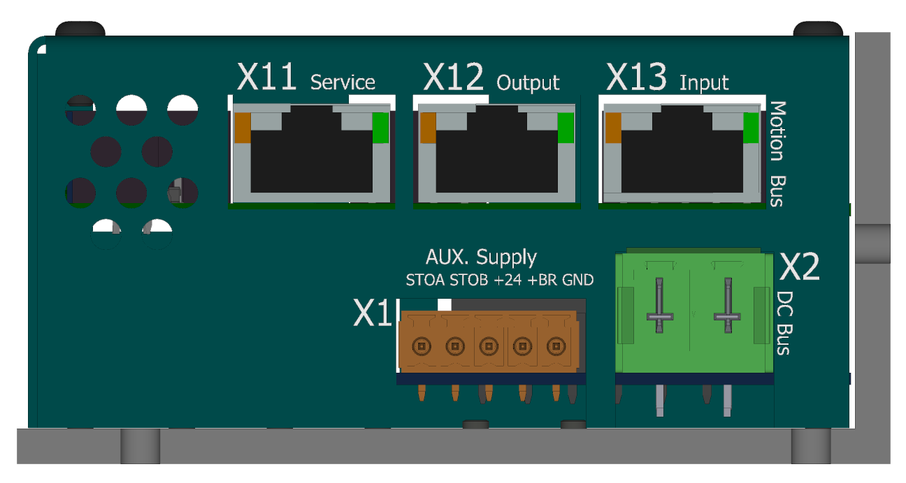
Connectors
View of the ENET/ECAT side
-
X1 - Control supply voltage

-
Weidmüller BCZ 3.81/05/180 SN OR BX
pin # Marking Description AWG 1 STO_A STO channel A 16 2 STO_B STO channel B 16 3 VCC +24V control supply 16 4 VCC_BR +24V brake supply 16 5 GND GND (0 V) 16 -
X2 - Power supply voltage (DC bus)

-
Phoenix Contact PC 5/ 2-STCL1-7,62
pin # Marking Description AWG 1 +DC 0 ~ +48VDC 10 2 -DC 0V (GND) 10 Regenerative braking
In cases when the drive is not powered by a battery (e.g., a Li-ion battery pack), it is necessary for machines with greater kinetic energy to ensure its dissipation, for example, in a resistive element using a chopper unit.
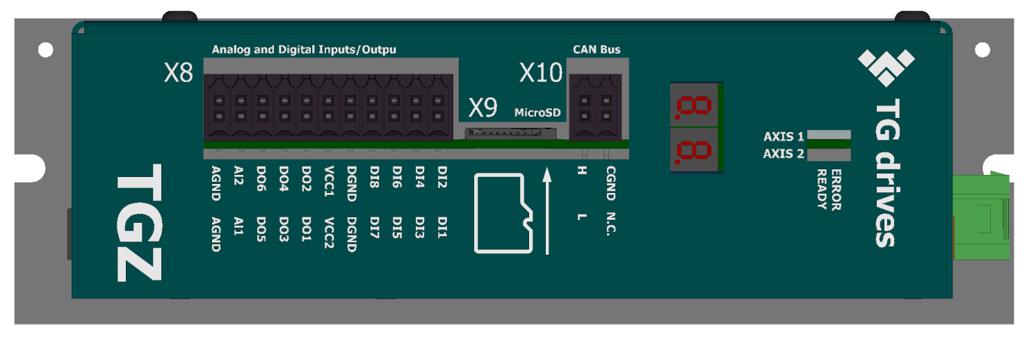
View of the CAN/IO/SD Side
-
X8 - Digital I/O, analog inputs
Cable side view
 3D view - cable side
  Front view (TGZ side)
Please see details about digital inputs DI1-8, digital outputs DO1-6 and analog inputs AI1-2 in the Common hardware section.
-
Weidmüller B2CF 3.50/22/180 SN OR BX
pin # Marking Description AWG 1 AGND Analog ground (internal) 16-25 2 AGND Analog ground (internal) 16-25 3 AIN2 Analog input no. 2 16-25 4 AIN1 Analog input no. 1 16-25 5 DO6 Digital output no. 6 16-25 6 DO5 Digital output no. 5 16-25 7 DO4 Digital output no. 4 16-25 8 DO3 Digital output no. 3 16-25 9 DO2 Digital output no. 2 16-25 10 DO1 Digital output no. 1 16-25 11 VCC DO2,4,6 Power for DO 2,4,6 (axis 2) 16-25 12 VCC DO1,3,5 Power for DO 1,3,5 (axis 1) 16-25 13 DGND Digital (iso) ground 16-25 14 DGND Digital (iso) ground 16-25 15 DI8 Digital input no. 8 16-25 16 DI7 Digital input no. 7 16-25 17 DI6 Digital input no. 6 16-25 18 DI5 Digital input no. 5 16-25 19 DI4 Digital input no. 4 16-25 20 DI3 Digital input no. 3 16-25 21 DI2 Digital input no. 2 16-25 22 DI1 Digital input no. 1 16-25 Warning
For proper operation of the DI(1-6) it is necessary to supply at least one of the VCC DO (pin 11 and 12). Inputs DI7,8 are independent of the DO VCC supply voltage and work correctly even without it.
-
X9 - MicroSD card
-
Use a standard microSD card. The card is included with the TGZ servo amplifier. For more information, see SD cards.
-
X10 - CAN
Cable side view

3D view - cable side

Front view (TGZ side)

-
Weidmüller B2CF 3.50/04/180 SN OR BX
pin # Marking Description AWG 1 CANH CAN signal H 16-25 2 CANL CAN signal L 16-25 3 CANGND CAN isolated ground 16-25 4 NC No connection 16-25 For more information on the HW version of the CAN bus, see CAN bus.
-
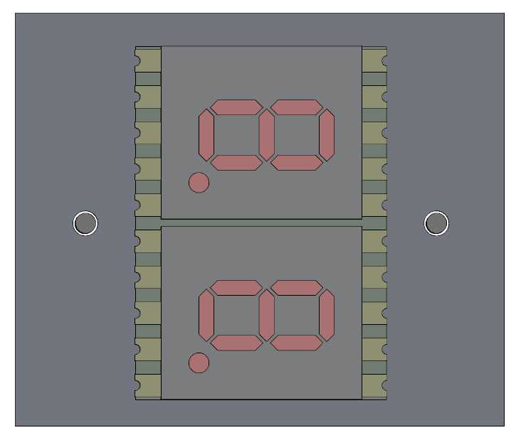
LED display
-
LED display indicates the status of the servoamplifier. See TGZ status indicators for detailed description.
-
status LEDs

-
LED diodes
LED color Status green Servo OK red Servo Error A complete description of the meaning of the status LEDs can be found here: TGZ status indicators
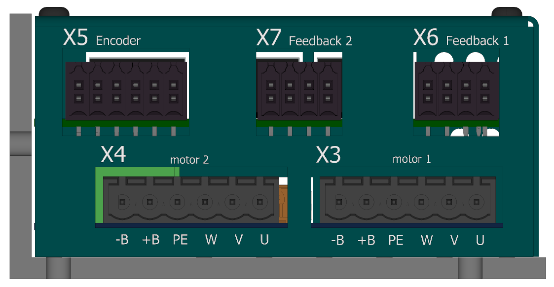
View of the FB/motor side
-
X5 - External encoder (FBE)
Cable side view

3D view - cable side

Front view (TGZ side)

-
Weidmüller B2CF 3.50/12/180 SN OR BX
pin # Endat 2.2/SSI/BISS Hiperface DSL Incremental encoder 1 GND GND GND 2 +5 V +5V +5V 3 ZERO- N.C. Z- 4 ZERO+ N.C. Z+ 5 N.C. FBSEL- N.C. 6 N.C. FBSEL+ N.C. 7 DATA- FBSEL- A- 8 DATA+ FBSEL+ A+ 9 CLK- N.C. B- 10 CLK+ N.C. B+ 11 GND DSL- GND 12 +12 V DSL+ +12 V For more information on external feedback, see FBE Feedback.
-
X6 - Feedback axis 1
Cable side view

3D view - cable side

Front view (TGZ side)

-
Weidmüller B2CF 3.50/08/180 SN OR BX
pin # Endat 2.2/SSI/BISS Hiperface DSL Incremental encoder 1 N.C. FBSEL- N.C. 2 N.C. FBSEL+ N.C. 3 DATA- FBSEL- A- 4 DATA+ FBSEL+ A+ 5 CLK- N.C. B- 6 CLK+ N.C. B+ 7 GND DSL- GND 8 +12 V DSL+ +12 V For more information regarding Feedback 1, please see Feedback FB1, FB2.
-
X7 - Feedback axis 2
Cable side view
3D view - cable side
Front view (TGZ side)
-
Weidmüller B2CF 3.50/08/180 SN OR BX
pin # Endat 2.2/SSI/BISS Hiperface DSL Incremental encoder 1 N.C. FBSEL- N.C. 2 N.C. FBSEL+ N.C. 3 DATA- FBSEL- A- 4 DATA+ FBSEL+ A+ 5 CLK- N.C. B- 6 CLK+ N.C. B+ 7 GND DSL- GND 8 +12 V DSL+ +12 V For more information regarding Feedback 2, please see Feedback FB1, FB2.
-
X3 - Motor connector - axis 1

Holding motor brake
For additional information on using the motor brake with the TGZ servo drive, see the Standard Brake section.
-
Weidmüller BLZP 5.08HC/06/180 SN OR BX
pin # Marking Description AWG 1 -B - Brake 4-24 2 +B + Brake 4-24 3 PE Protect earth 4-24 4 W Phase W 4-24 5 V Phase V 4-24 6 U Phase U 4-24 -
X4 - Motor connector - axis 2
Holding motor brake
For additional information on using the motor brake with the TGZ servo drive, see the Standard Brake section.
-
Weidmüller BLZP 5.08HC/06/180 SN OR BX
pin # Marking Description AWG 1 -B - Brake 4-24 2 +B + Brake 4-24 3 PE Protect earth 4-24 4 W Phase W 4-24 5 V Phase V 4-24 6 U Phase U 4-24