Device description
3D view


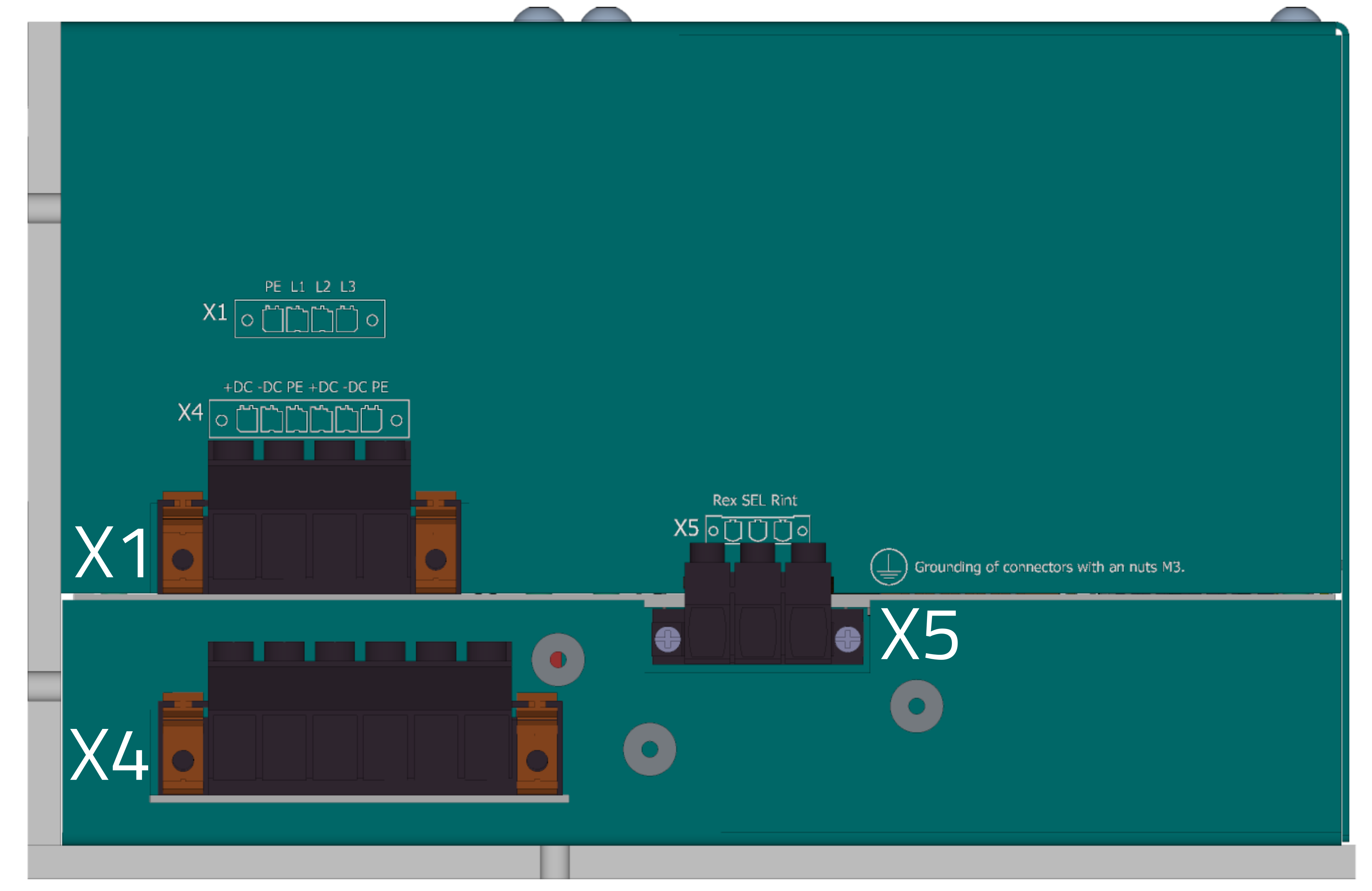
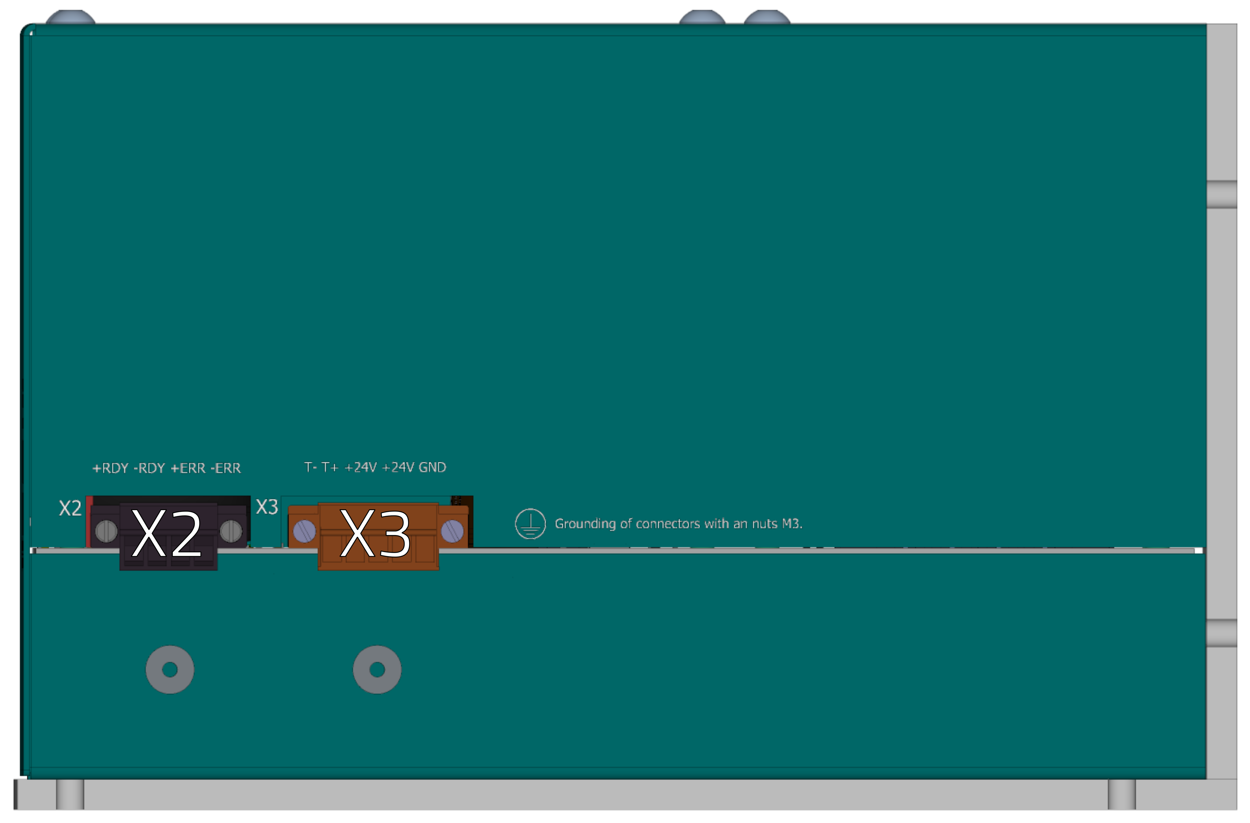
Connectors
Power connectors side
-
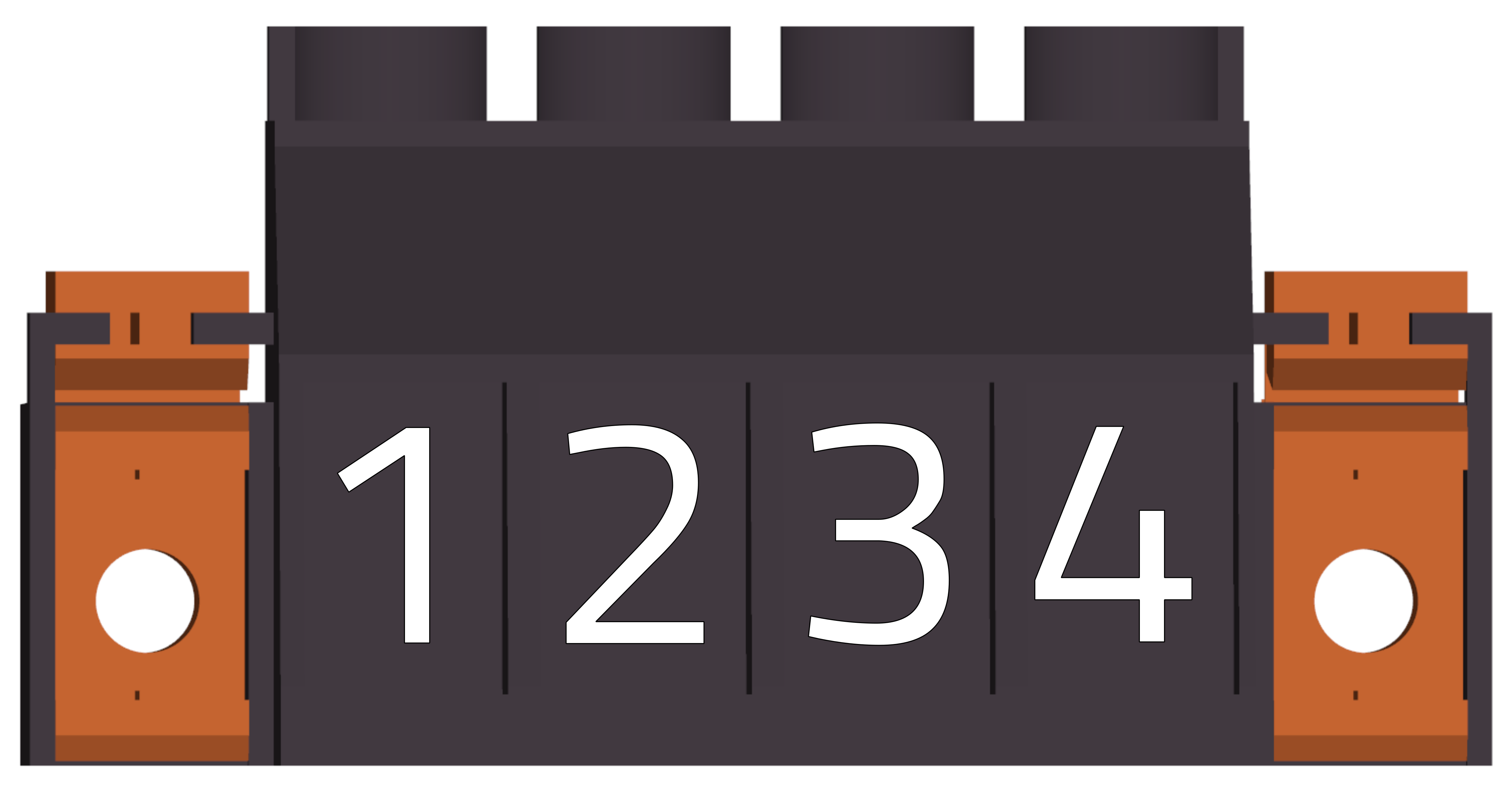
X1 - Mains connector
Cable side view
-
WEIDMÜLLER BVZ 7.62HP/04/180F
pin # Marking Description AWG 1 PE Ground 24~8 2 L1 Phase 1 24~8 3 L2 Phase 2 24~8 4 L3 Phase 3 24~8 -
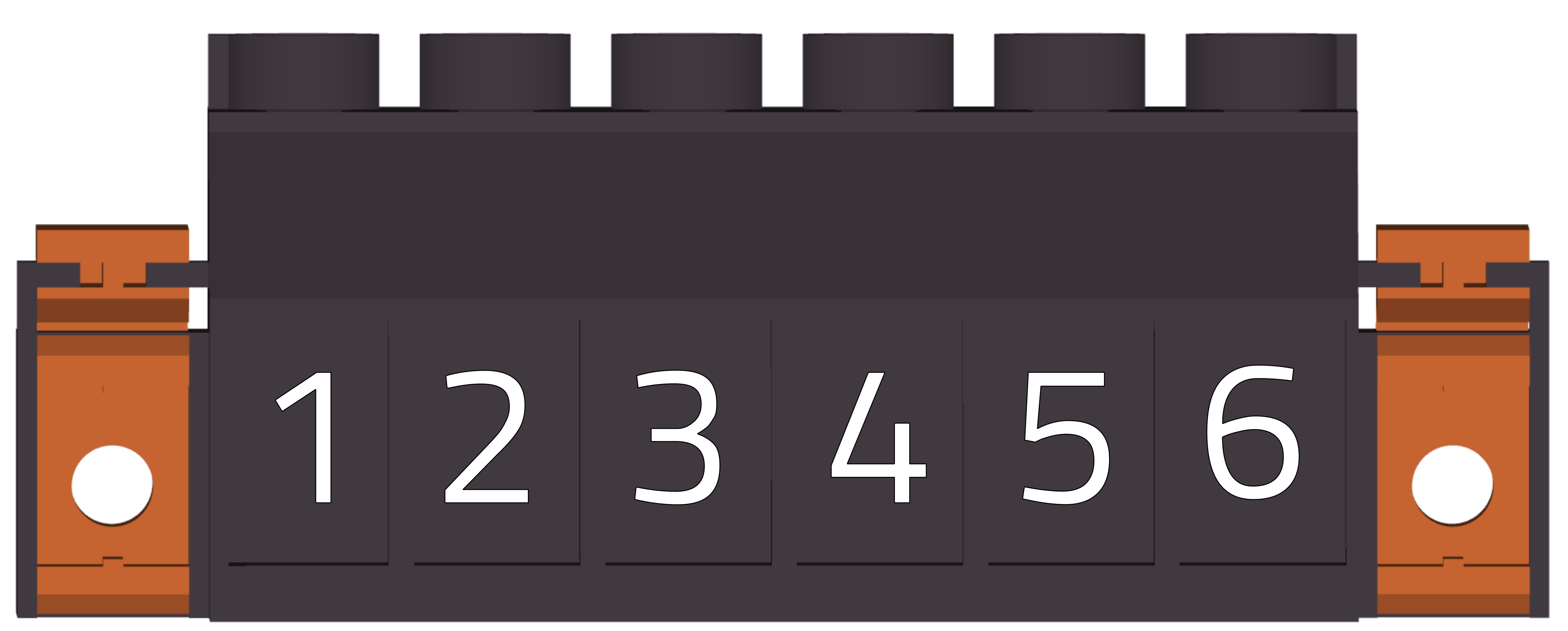
X4 - DC bus connector
Cable side view
-
WEIDMÜLLER BVZ 7.62HP/06/180F
pin # Marking Description AWG 1 +DC + DC bus out 24~8 2 -DC - DC bus out 24~8 3 PE Ground 24~8 4 +DC + DC bus out 24~8 5 -DC - DC bus out 24~8 6 PE Ground 24~8 -
X5 - Brake resistor
Cable side view
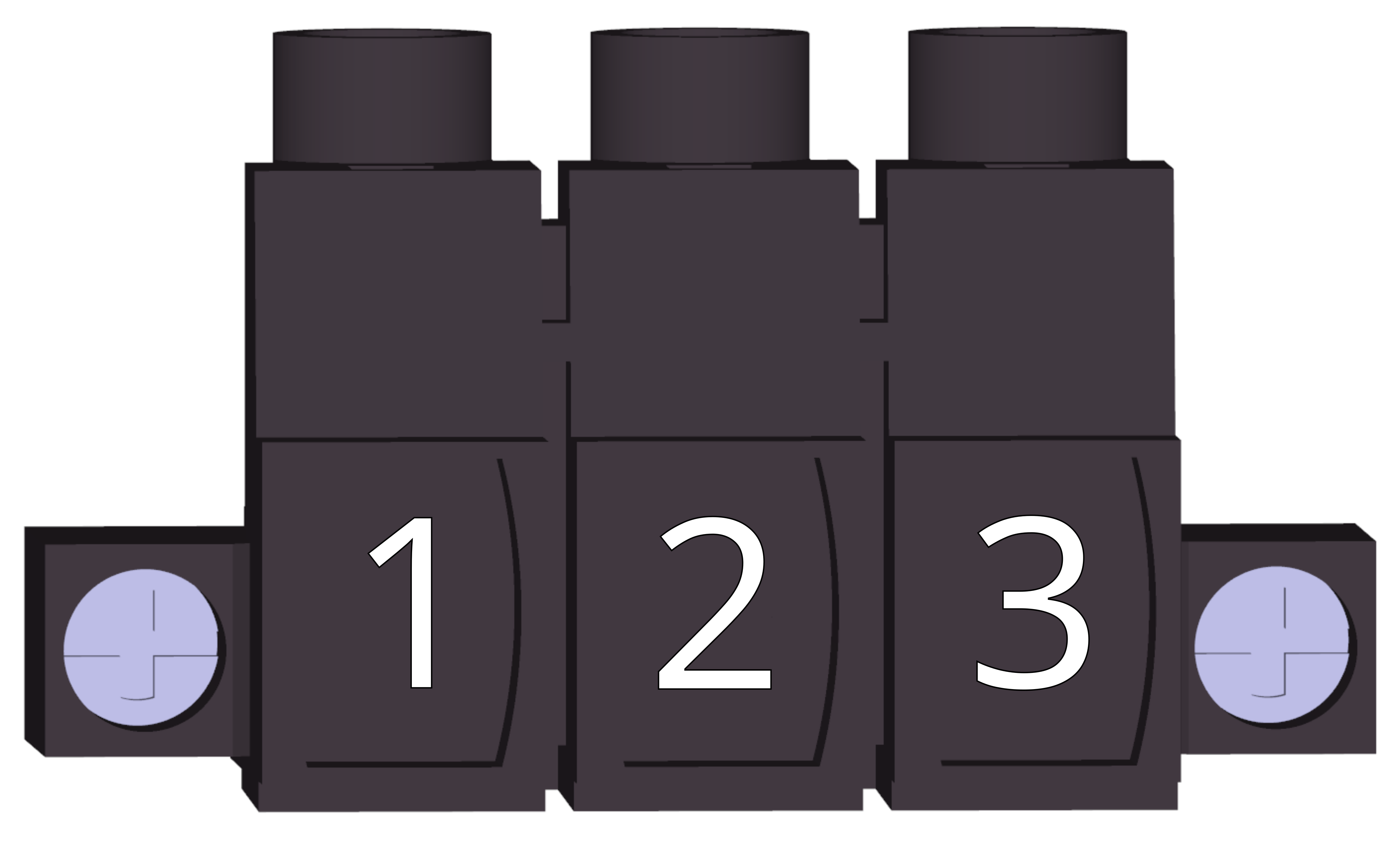
The X5 connector comes with jumper wires prepared for use with the internal chopper resistor.

If an external chopper (brake) resistor is used, the jumper wires must be removed from both X5 and X3 connectors and the resistor connected according to the schematic.
-
WEIDMÜLLER BLZ 7.62HP/03/180F
pin # Marking Description AWG 1 RBin Internal regen. resistor 28 ~ 12 2 SEL Brake resistor select 28 ~ 12 3 RBex External regen. resistor 28 ~ 12
Logic power side
-
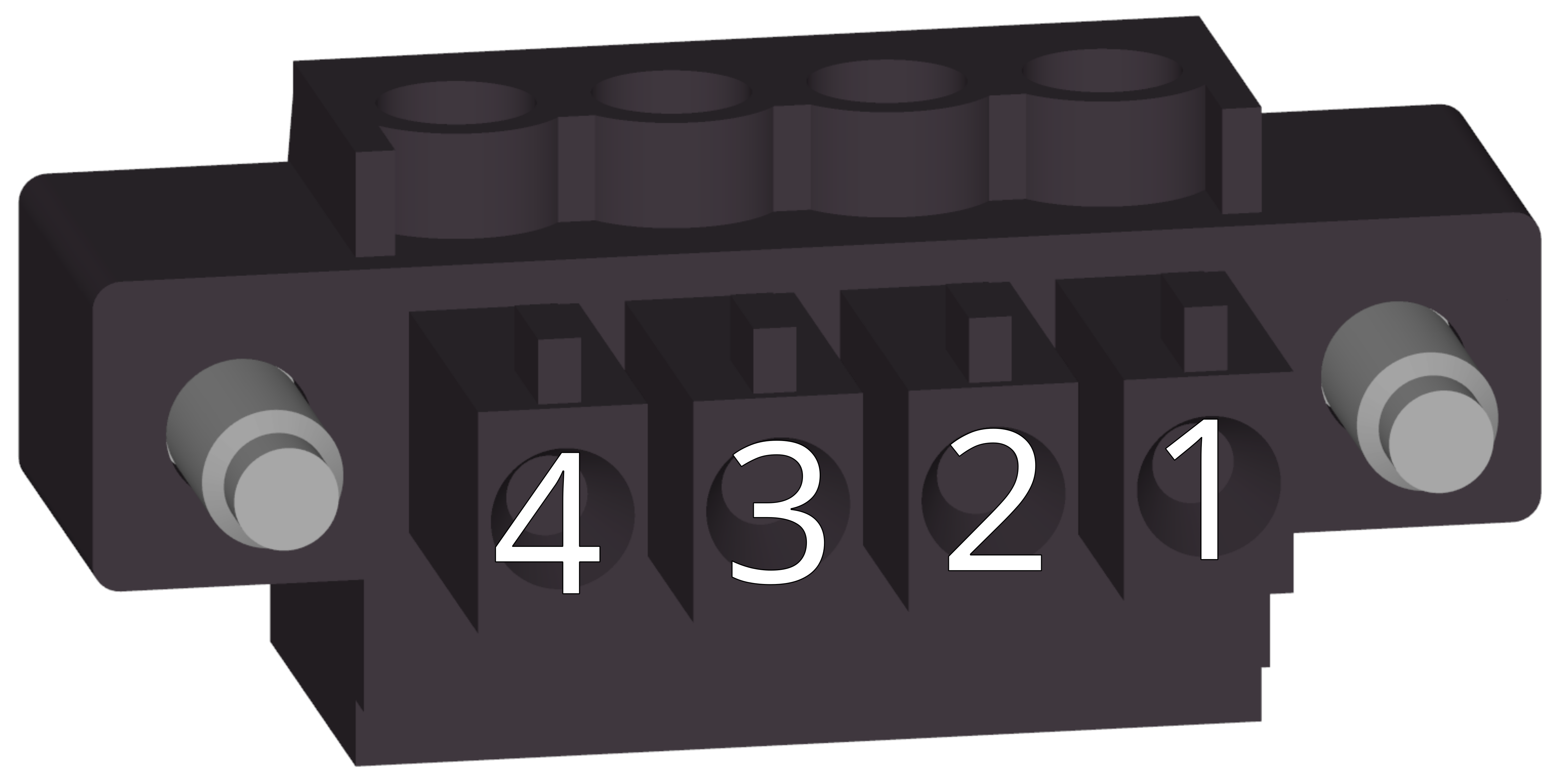
X3 - Logic power
Cable side view
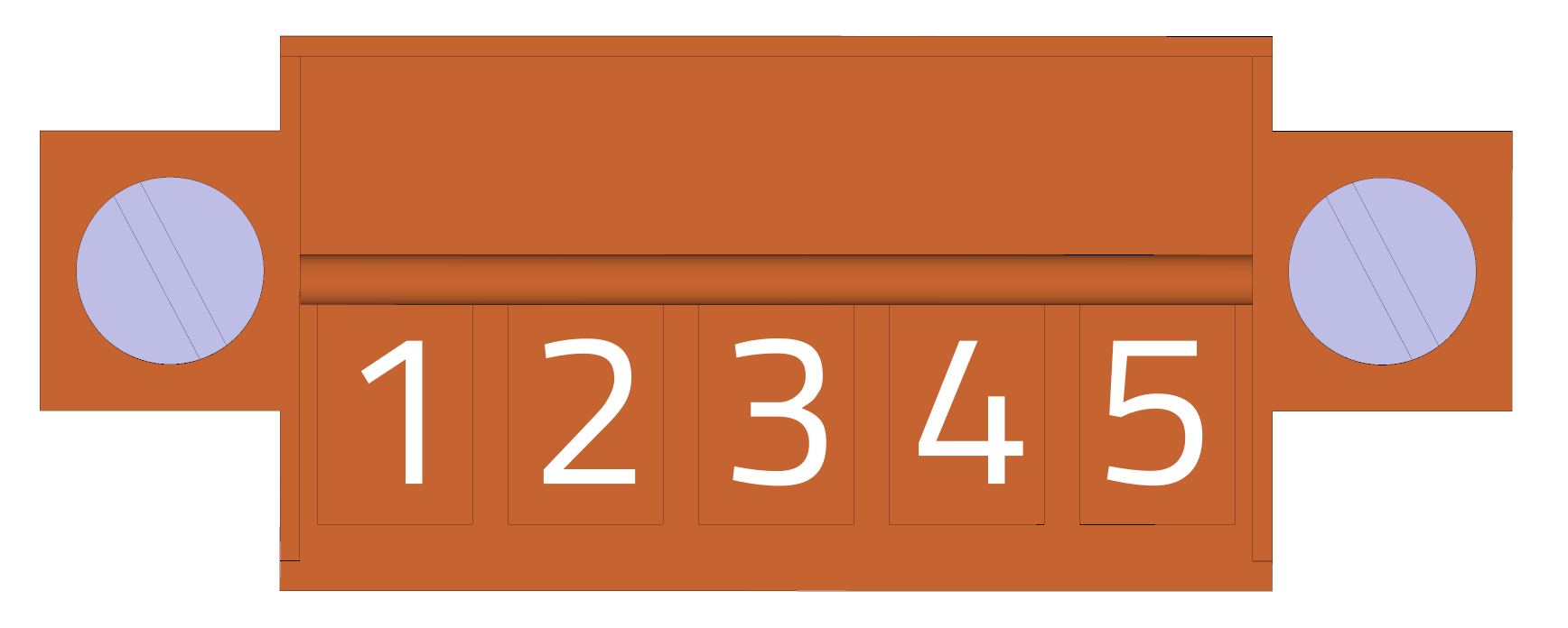
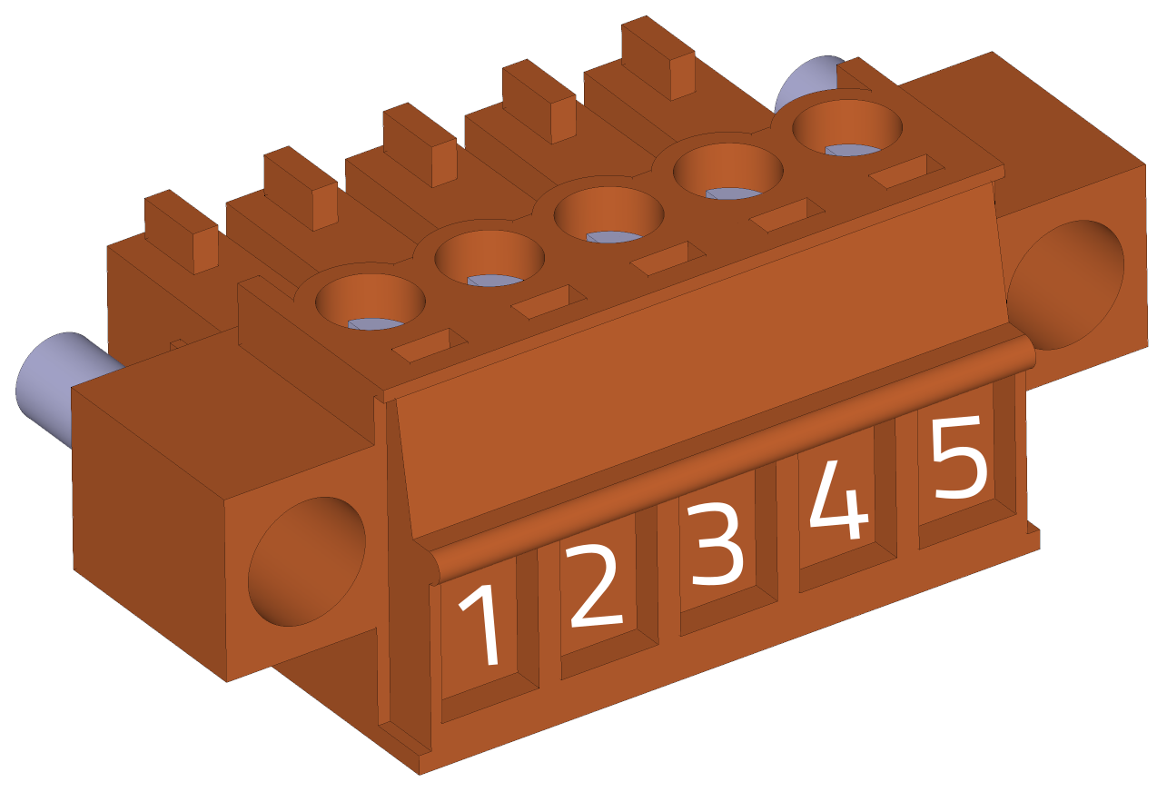
The X3 connector comes with jumper wires prepared for use with the internal chopper resistor.

If an external chopper (brake) resistor is used, the jumper wires must be removed both from the X3 and X5 connectors and the resistor connected according to the schematic.
-
Weidmüller BCZ 3.81/05/180F SN OR BX
pin # Marking Description AWG 1 TERM1 Thermistor input 1 (positive) 16~28 2 TERM2 Thermistor input 2 (negative) 16~28 3 VCC +24V logic power 16~28 4 NC NC 16~28 5 GND GND (0 V) 16~28 -
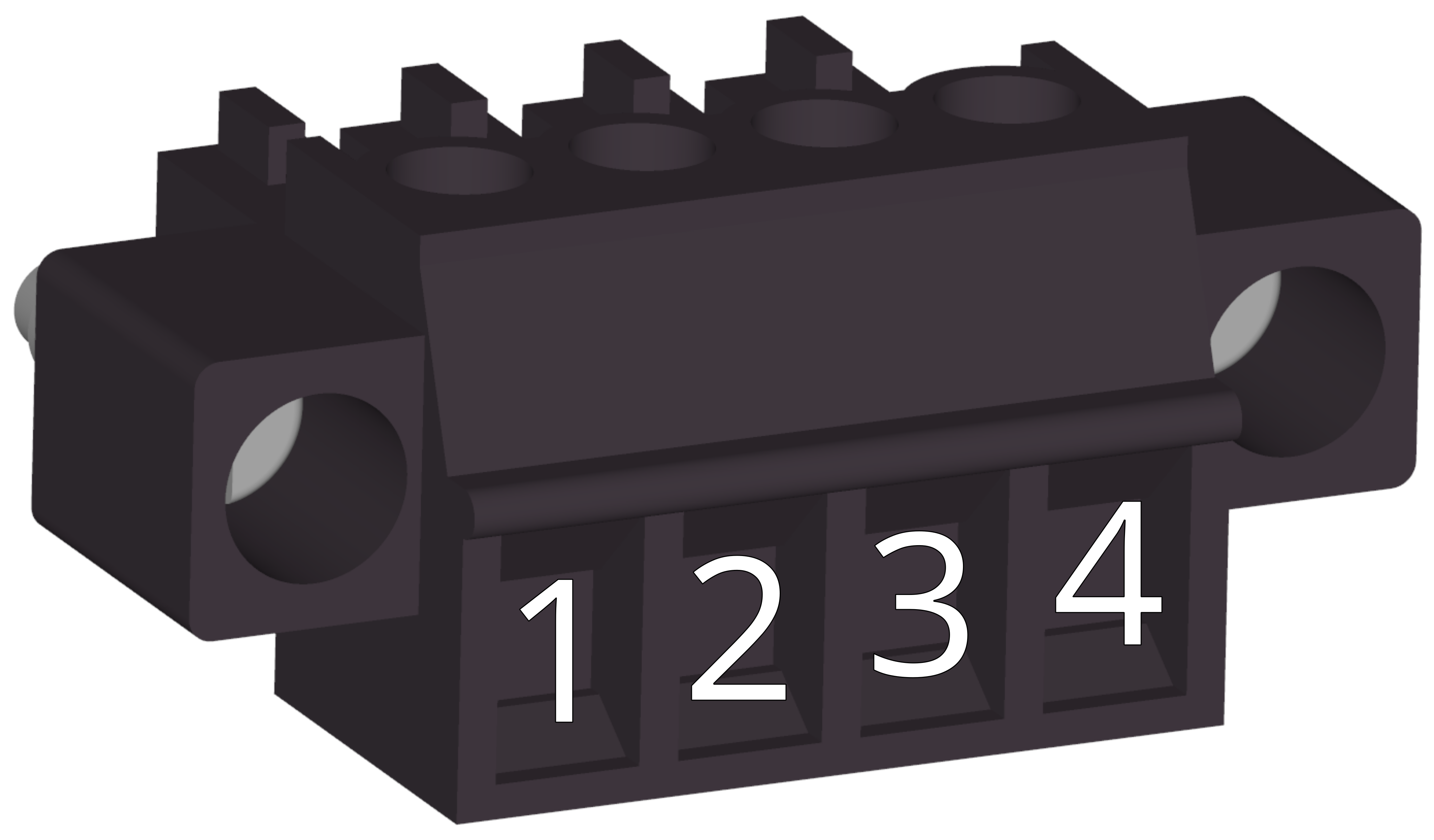
X2 - Control outputs
Cable side view
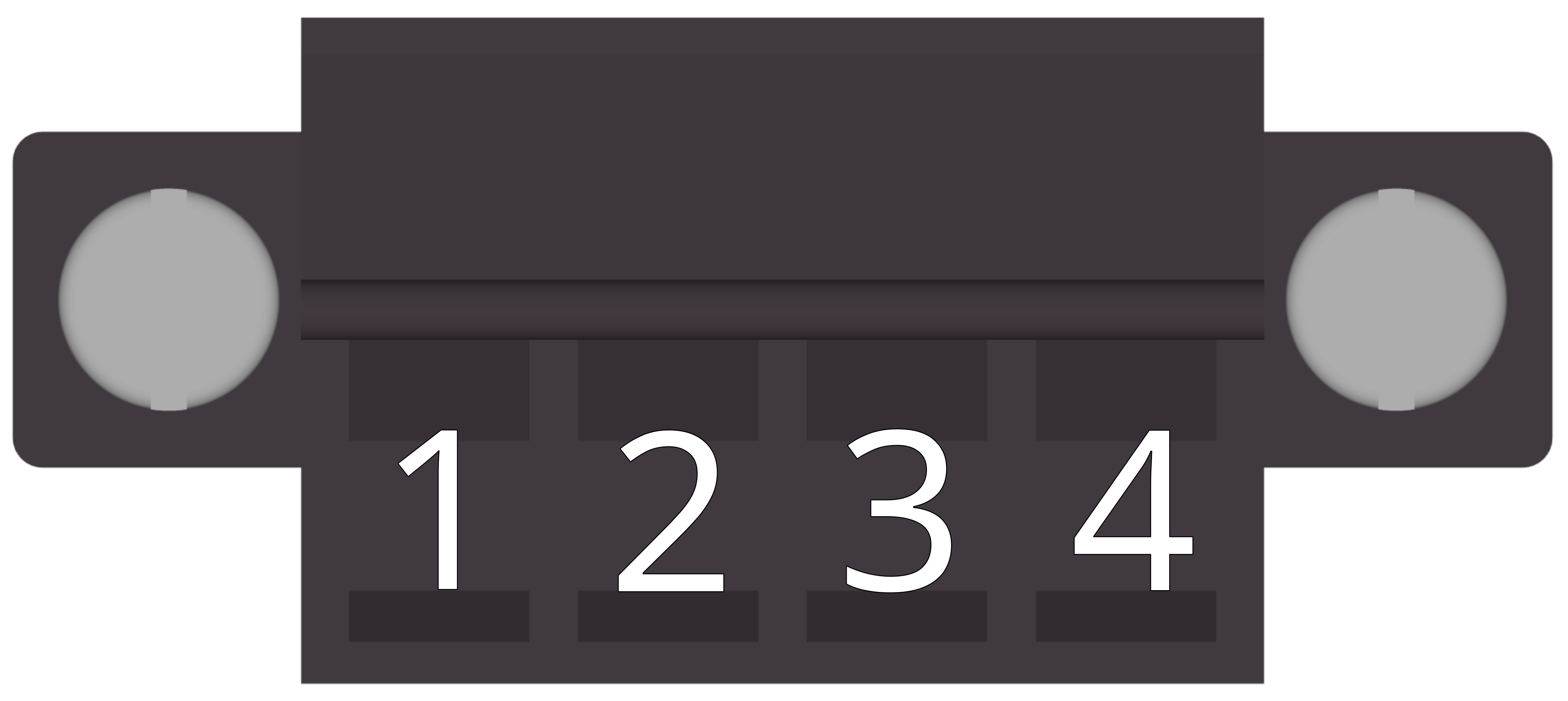
Front view (TGS side)
-
Weidmüller BCZ 3.81/04/180 SN BK BX
pin # Marking Description AWG 1 RDY1 signal „Ready“ contact 1 16-24 2 RDY2 signal „Ready“ contact 2 16-24 3 ERR1 signal „Error“ contact 1 16-24 4 ERR2 signal „Error“ contact 2 16-24
Mode selector side
-
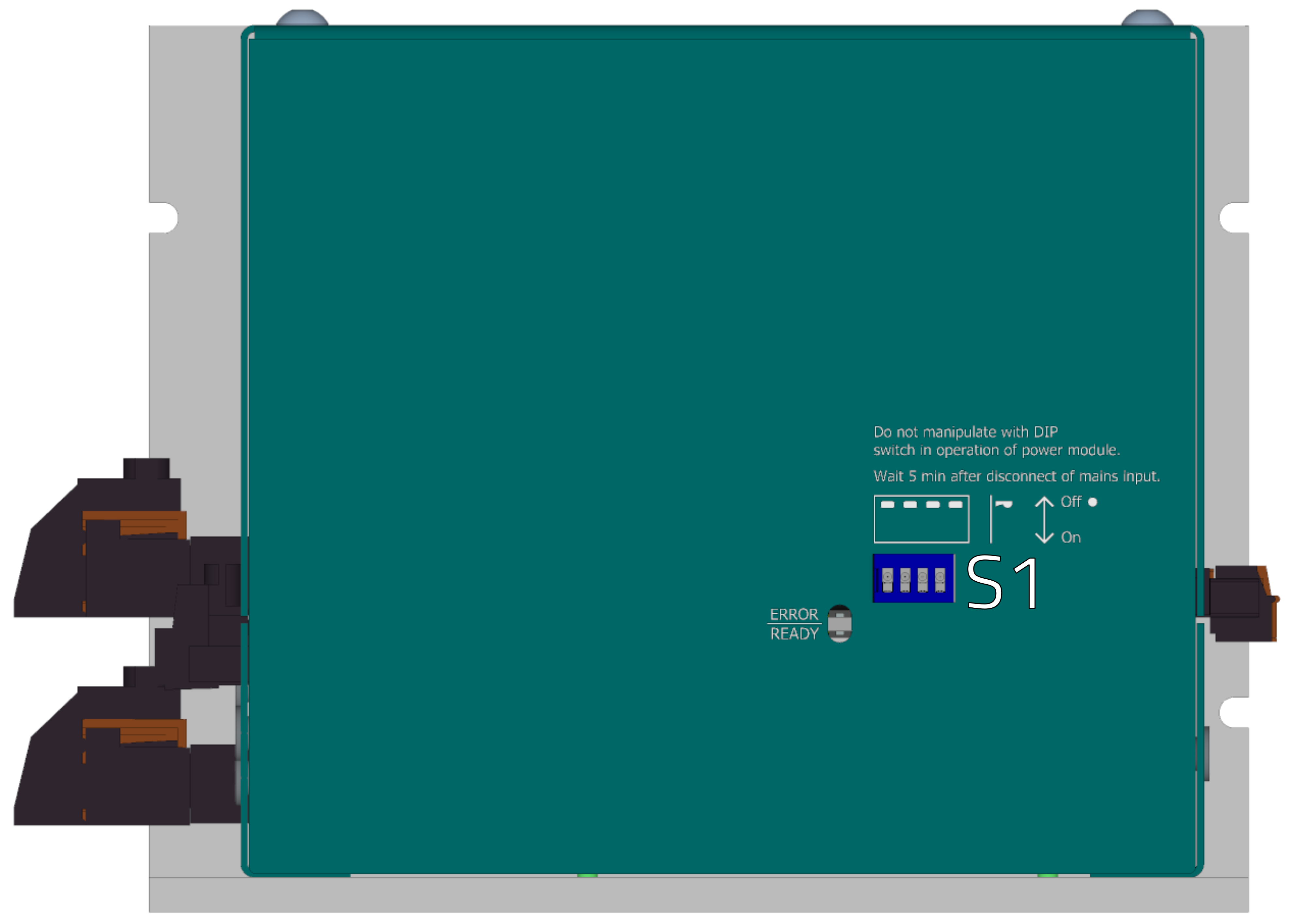
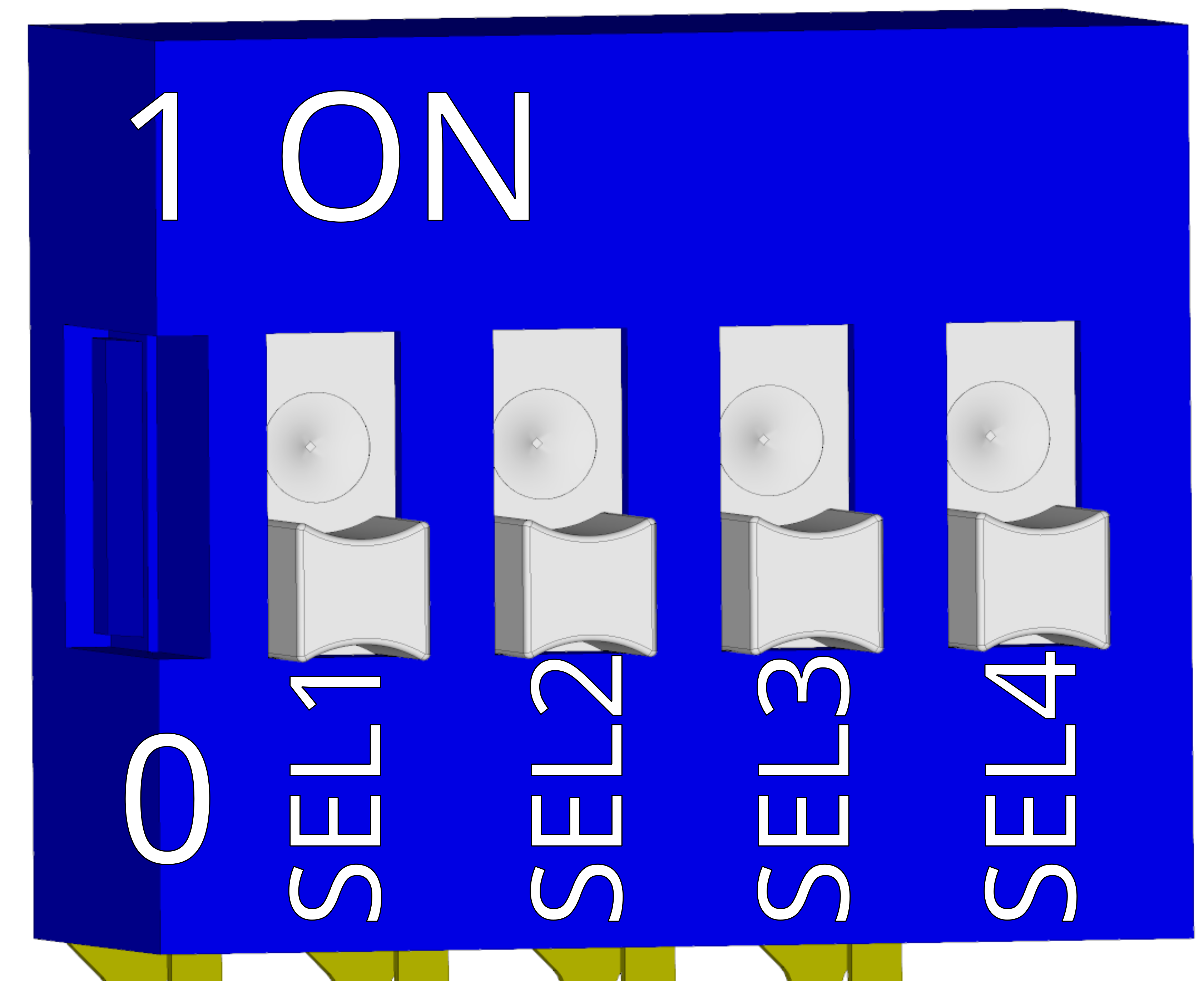
S1 - Mode select
-
4 position DIP switch
Position Function Description SEL1 1st code bit – MSB 1000 SEL2 2nd code bit 0100 SEL3 3rd code bit 0010 SEL4 4th code bit – LSB 0001 Selected 4 bit. code Meaning – mode 0000 default 0001 reserved 0010 reserved 0011 reserved 0100 reserved 0101 reserved 0110 reserved 0111 reserved 1000 reserved 1001 reserved 1010 reserved 1011 reserved 1100 reserved 1101 reserved 1110 reserved 1111 reserved -
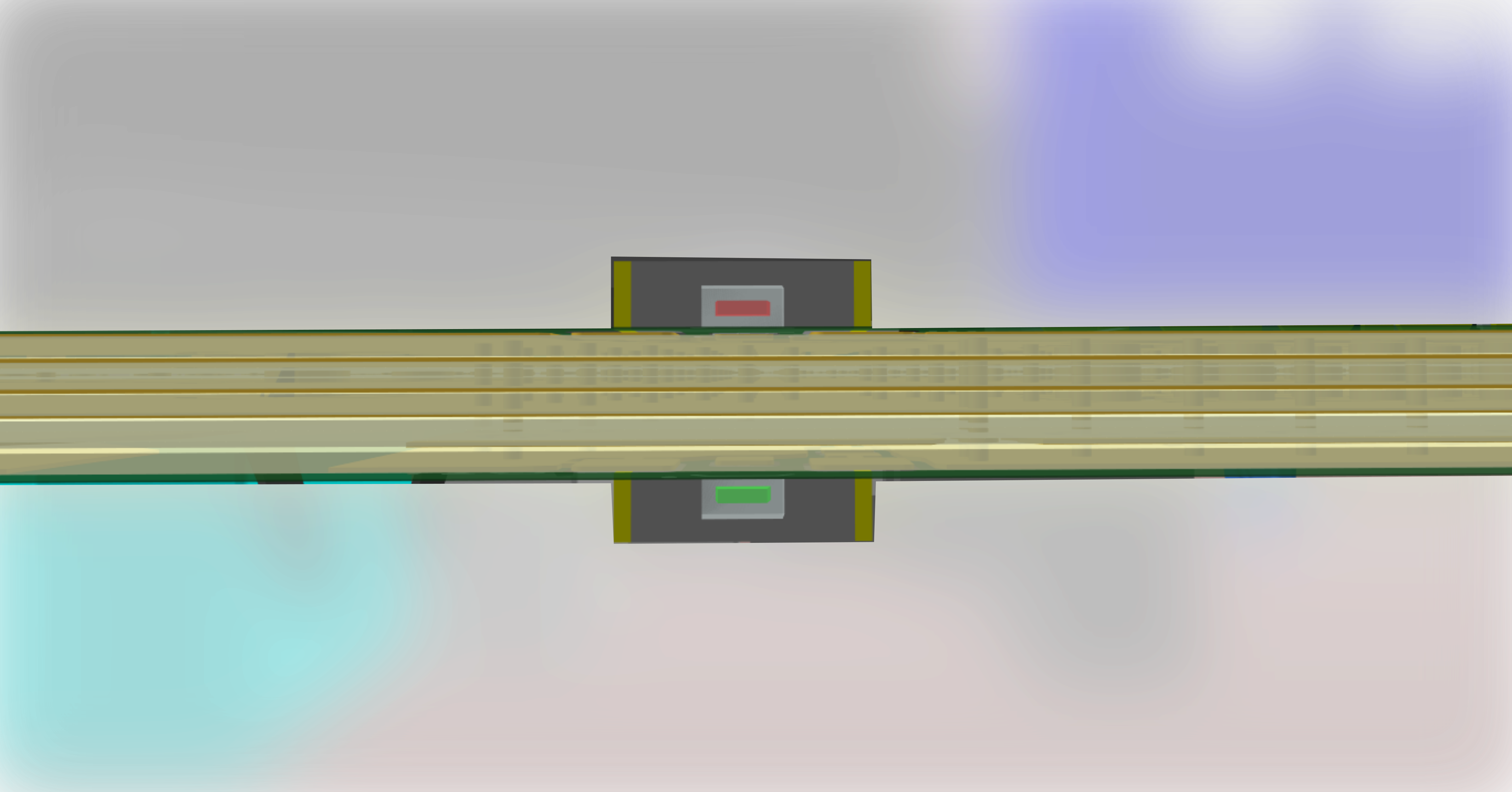
LED signalization
-
LED
Red LED Number of flashes Description short flash 1 Dcbus undervoltage short flash 2 Dcbus overvoltage short flash 3 Mains error short flash 4 internal overtemperature short flash 5 softstart overtemperature short flash 6 brake resistor overtemperature short flash 7 reserved short flash 8 reserved permanently on - DCbus undervoltage + mains error. Softstart disabled. No other errors. Green LED Description permanently on device ready, no errors permanently off device not ready