PROFIdrive
Telegram assignment
The TGZ drive supports the following telegrams for PROFIdrive communication:
| Telegram number | Description |
|---|---|
| 1 | Speed control mode (16-bit) |
| 3 | Speed control mode with actual position (32-bit) (standard firmware only) |
| 7 | Position control mode (tasks only) |
| 9 | Position control mode (tasks and direct MDI control) |
| 102 | Speed control mode with extended features (PROFIsafe firmware only) |
| 111 | Position control mode with extended features (MDI control) |
| 352 | Speed control mode with extended features |
Warning
The telegrams must be selected using TGZ_GUI application. When changed, the TGZ must be restarted. It is important that the PLC has already the right telegrams selected in the project and it is running before the TGZ is restarted, otherwise the drive will not be able to establish communication with the PLC and will not work. This behaviour is important only when the telegrams are changed, otherwise the power up order of PLC and TGZ does not matter.
Homing modes
The drive must be in operational state with positioning mode set (telegrams 7, 9 or 111). No task must be active and the drive must be in standstill. The mode is selected by the Homing_Mode parameter in the TGZ_GUI application. To initiate a homing procedure, set the control word STW1 bit 11 to one. As the homing procedure is running, the status word ZSW1 bits 10, 11 and 13 are set to zero. After successful homing, these bits 10, 11 and 13 go to one. In the case of any error during homing, only the bit 13 is set. The homing procedure can be aborted by setting the STW1 bit 11 to zero. It is also necessary to finish the successful homing procedure by setting the STW1 bit 11 to zero. Only after this the drive goes back to the basic operational state.
The following homing modes are available:
| Mode no. | Mode description |
|---|---|
| 0 | Set zero to the actual position. Uses the actual position as the home point reference. |
| 1 | Find limit input. Movement starts in positive or negative direction until the limit switch is detected. Then the reverse movement is used until the limit switch is no longer active. The actual position is used as the home point. Homing_NegLimSwitchMask and Homing_PosLimitSwitchMask parameters are used to select the digital input bit of the limit switch. The sign of Homing_Velocity_Direction parameter determines the homing direction. |
| 2 | Find limit input, then zero angle. Similar to mode 1, but after the home position is set, the motor moves to the zero angle of the feedback. |
| 4 | Find home input. This mode is similar to mode 1, but uses the homing switch as the input (parameter Homing_ReferenceSwitchMask). The initial direction is determined by the sign of Homing_Velocity_Direction parameter. The positive and negative switches are also taken into account in the algorithm. |
| 5 | Find home input, then zero angle. Similar to mode 4, after the home position is set, the drive goes to the zero angle of the feedback. |
| 8 | Move to mechanical stop. The drive moves until it encounters a hard stop, causing the position error to be exceeded. The move stops afterwards and the home position is set. |
| 9 | Move to mechanical stop, then zero angle. Similar to mode 8, after the home position is set, the motor moves to the zero angle of the feedback. |
Tasks
The TGZ amplifier allows up to ten tasks to be used in positioning mode. The task numbers are set by the SATZANW signal in telegrams 7, 9 or 111. The task parameters can be set by TGZ_GUI. The target position is always 64 bits (in TGZ units) to allow full value precision. The mode of the task is either 0 - relative positioning, or 1 - absolute target value. No action is performed for invalid task numbers. Valid values are 0 - 9 (PD_Task1 - PD_Task10). For a detailed description of the task and direct Manual data input (MDI) mode, see the PROFIdrive Profile documentation.
Jog
The jogging function is supported in both position (telegrams 7, 9, 111) and speed mode (telegrams 1, 3, 352). All the jog parameters can be set by the TGZ_GUI application. Two jog setpoints are available by using the control word STW1 bits 8 and 9. If both bits are set the drive either stops in speed mode or does nothing in positioning mode.
The drive works in speed mode when the jog is active, i.e., it moves the axis with the desired jog speed endlessly until stopped.
The functionality is implemented according to the standard described in the PROFIdrive Profile documentation.
Fault buffer
TGZ follows the standard PROFIdrive fault buffer mechanism. Since a standard fault buffer entry is 16 bits wide, but TGZ uses 32-bit fault numbers, each error situation occupies two consecutive entries in the buffer (PNU 947). The buffer can store up to eight error situations, forming a 16-entry array (each entry being 2 bytes long). To read an error situation, the parameter index is used. Since each error spans two 16-bit values, two reads are necessary:
- Even index → Lower 16 bits of the error
- Odd index → Upper 16 bits of the error
Typically, indexes 0 and 1 are used to retrieve the most recent error.
Reading Faults
PROFIdrive supports multi-register reads, allowing efficient fault retrieval. The SinaPara function block can be used as follows:
- Set
sxParameter[0].siParaNo = 947andsxParameter[1].siParaNo = 947(PNU number). - Set
sxParameter[0].siIndex = 0andsxParameter[1].siIndex = 1. - Set
ParaNo = 2(to read two parameters). - TGZ automatically sets the read format to 16#42 (42h means 16-bit word value).
Alternatively, the SinaParaS function block can be used for a simpler implementation.
Fault Counters
- PNU 944 (Fault Message Counter): Incremented by 2 for each new error situation.
- PNU 952 (Fault Situation Counter): Incremented by 1 per new error.
Acknowledging Errors
When an error is acknowledged via bit 7 of the control word, the fault buffer shifts down, removing the most recent error. The fault buffer can be completely cleared by writing zero to the parameter PNU952. For more details, refer to the PROFIdrive Profile Manual.
Error codes
The error code is copied to the fault buffer in the case of any drive error. The standard PROFIdrive fault buffer mechanism is used. Because the standard PROFIdrive error code has a width of 16 bits only and TGZ uses 32-bit errors, there are always two fault messages containing the full 32-bit error word. Therefore, the parameter 947 is organized with 8 fault situations with 2 fault messages. The message with index 0 contains the low 16 bits of the error code and the message with index 1 the high 16 bits.
The fault buffer can be completely cleared by writing zero to the parameter 952.
Telegram 111 contains space for the last active error code, where the WARN code field (PZD11) contains the low 16 bits and the FAULT code field (PZD10) contains the high 16 bits of the TGZ error code. Similarly, the telegram 352 has fields for WARN (PZD5) and FAULT (PZD6). They are coded in the same manner. The TGZ error codes are bit-oriented, i.e., there are up to 32 errors possible, and they are cumulative, i.e., several bits can be set at the same time.
| Bit | Description |
|---|---|
| 2 | reserved (internal error) |
| 3 | Over voltage DC-Link |
| 4 | Under voltage DC-link |
| 5 | STO diagnostics or safety error |
| 6 | Holding brake error |
| 9 | Motor temperature |
| 11 | Drive temperature |
| 12 | Feedback |
| 14 | Over speed |
| 15 | Position error (countouring) |
| 17 | Fieldbus (loss of communication) |
| 19 | Current regulator error |
| 20 | Emergency stop |
| 21 | Driver saturation |
| 22 | Regen power |
| 27 | Invalid parameter |
Relationship between TGZ coordinates and PROFIdrive values
The TGZ drive uses 64-bit values for position. This value consists of number of revolutions in upper 32 bits, and number of increments within one turn.
On the other hand, PROFIdrive standard uses only 32-bit values for position. For this reason, some kind of up and downscaling is necessary.
The wanted position value from PROFIdrive telegram is expanded to 64 bits and then shifted left by 32 minus the number of bits specified in the TGZ settings – Profile generator (PG) value BitsPerRevol.
If BitsPerRevol=20, then the value from PROFIdrive is shifted left by 12 bits. The shifting has the same effect as multiplying the value by 2^12 (i.e., 4096).
The similar downscaling is performed when sending actual position value from TGZ to the PROFIdrive controller: the 64-bit TGZ position is shifted right by 32 - BitsPerRevol (which is the same operation as dividing by 232-BitsPerRevol) and the resulting lower 32 bits are sent in the PROFIdrive telegram.
The values of velocity are not scaled at all because both TGZ and PROFIdrive telegrams use 32-bit values. Therefore, the meaning of velocity is the same as velocity for the Profile generator. Acceleration and deceleration must be set directly in the TGZ by service program TGZ_GUI in the PROFIdrive section and can be changed by PROFIdrive telegrams only by means of override (percentage) values contained in the respective telegrams.
Backlash compensation
The firmware from August 2023 or newer implements the backlash compensation. The standard parameter PNU 2583 is used for the backlash value.
It is stored as signed 32-bit integer value and has the same physical meaning as desired or actual position in telegrams 9 or 111.
To use the backlash compensation, a successful homing procedure must be performed first.
The positive movement direction is performed when the actual position is incremented. Likewise, the negative movement is defined when the position is decremented. The compensation itself is dependent on the sign of the backlash:
- Positive backlash value: when the wanted position is in the positive direction, the backlash value is added to the value. On the other hand, for the negative movement, no value is added to the desired position.
- Negative backlash value: during the negative movement the backlash is subtracted from the wanted position, making the result more negative. For the positive direction, no value is added to the final desired position.
Use of the positive or negative backlash depends on the chosen homing procedure and its final movement. If the homing finishes with the negative movement, use the positive backlash, because the looseness is already adjusted to the left side. Likewise choose the negative backlash value when the last homing movement goes in the positive direction.
The backlash value can be set only by the parameter PNU 2583 by PLC, there is no equivalent in the TGZ register area.
The program block called SinParaS can be used in the TIA portal for setting the PNU 2583.
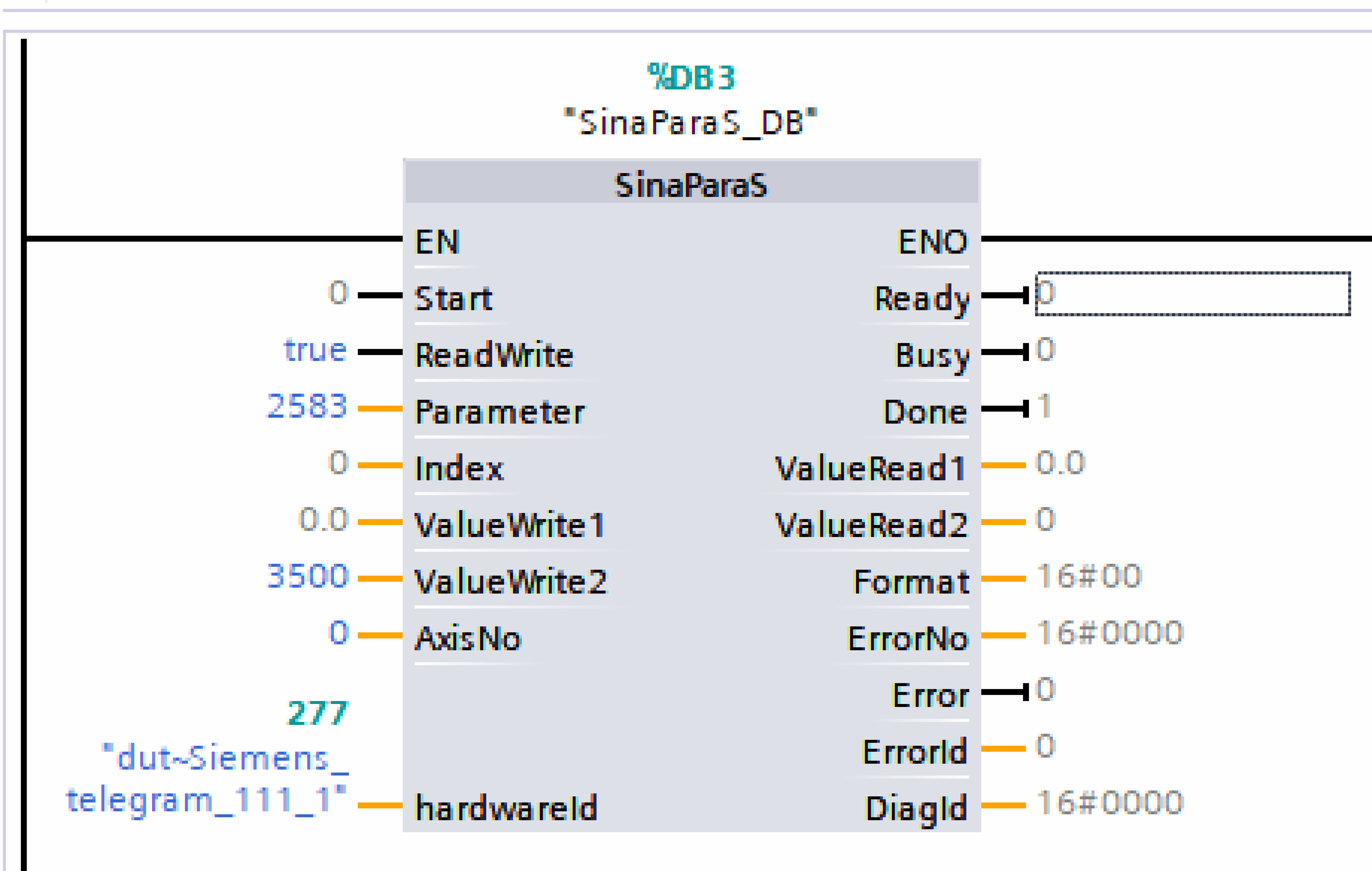
The hardwareId input is set to the same value as HWIDSTW input of SinaPos block, i.e., the telegram identifier of the TGZ. AxisNo can be 0 for the first axis or 1 for the second one.
As the backlash is of type DINT (signed 32-bit integer), the wanted backlash value must be written to the ValueWrite2 input.
The write is performed by toggling Start from False to True.
Speed control mode and normalized values
Telegrams 1, 3 and 352 are used for speed control mode. These telegrams use normalized speed values in the N2 or N4 format.
Setpoint and actual speed are expressed as a percentage of the reference value. TGZ amplifier uses the nominal speed register named M-Nn for this purpose – it must be non-zero, otherwise the speed control mode would not work.
Normalized N2 or N4 values in the telegram are in the range from -200 % to 200 % of the reference M-Nn value.
The M-Nn register can be read by the standard PNU parameter 60 000 Velocity reference value.
Complete access (read/write) is possible by direct TGZ parameters access, register numbers are 0x211B for axis 1 and 0x221B for axis 2.
See also chapter TGZ registers.
Note
Note that PNU 60 000 is read as floating point value, while direct access to TGZ registers is always 32-bit integer.
The internal speed profile generator uses register PD_Dec (0x355F / 0x365F) as the acceleration value when changing the speed.
PROFIdrive parameters
The TGZ servo drive supports parameter access through slots 1 and 2 (slot 2 for the variant with two axes only). Three record data object indexes can be used to access TGZ parameters:
47– legacy record data. The axis is specified directly in the request header.0xB02E– local base parameters access. The axis is specified by the slot performing the access.0xB02F– global base parameters access. The axis is specified directly in the request header.
Supported standard PROFIdrive PNUs
The TGZ servo drive supports the following standard and mandatory PROFIdrive parameters (PNUs):
| Number | Description | Data type |
|---|---|---|
| 922 | Telegram selection | Unsigned16 |
| 930 | Operating mode | Unsigned16 |
| 944 | Fault message counter | Unsigned16 |
| 947 | Fault number | Array of Unsigned16 |
| 964 | Drive unit identification | Structure |
| 965 | Profile identification | Structure |
| 975 | Drive object identification | Structure |
Reference values PNU
| Number | Description | Data type | TGZ register name | TGZ register number |
|---|---|---|---|---|
| 2000 | Reference speed | Float32 | M-Nn | 0x2118, 0x2218 |
| 2001 | Reference voltage | Float32 | M-Un | 0x2117, 0x2217 |
| 2002 | Reference current | Float32 | M-In | 0x211B, 0x221B |
| 2003 | Reference torque | Float32 | M-Mn | 0x2119, 0x2219 |
| 2007 | Reference acceleration | Float32 | PG-PD_Acc | 0x395E, 0x3A5E |
Additional PROFIdrive parameters
| Number | Description | Data type |
|---|---|---|
| 2583 | Backlash compensation | Signed32 |
The parameter numbers from 2010 to 8191 are reserved for future firmware extensions. PNU 2583 is used for backlash compensation and is unique for each axis.
TGZ registers
All TGZ registers are accessible as manufacturer-specific PROFIdrive registers, starting from number 0x2000 (8192 DEC). The list of usable registers can be downloaded from the TG Drives website. Parameters are grouped into categories such as common, motor, drive, profile generator, etc. Groups and parameters within groups are numbered starting from zero. For example, parameter number 0x2119 belongs to group 1 (Motor) with an index of 25 (0x19 = 25 DEC).
ProfiNET related parameters
TGZ parameter names and their corresponding ProfiNET names and descriptions:
| TGZ parameter name | ProfiNET name | Description | Number for axis 1 | Number for axis 2 |
|---|---|---|---|---|
| PD_TelegramNumber | Telegram selection (PNU922) | Selects telegram | 0x2321 | 0x2421 |
| PD_DisplayInfo | - | Displays debugging messages on TGZ GUI output | 0x2323 | N/A |
| PD_SetDataCounter | - | Counts cyclic ProfiNET messages from I/O controller | 0x2324 | 0x2424 |
| PD_StatusWord_ZSW1 | Status word 1 (ZSW1) | Copy of PROFIdrive status word sent to I/O controller | 0x3500 | 0x3600 |
| PD_ControlWord_STW1 | Control word 1 (STW1) | - | 0x3501 | 0x3601 |
| PD_SATZANW | SATZANW | Selects traversing block | 0x3503 | 0x3603 |
| PD_AKTSATZ | AKTSATZ | Actual traversing block | 0x3504 | 0x3604 |
| PD_State | State diagram mode | State diagram mode | 0x3505 | 0x3605 |
TGZ supports up to 10 traversing blocks for independent use. Each block includes mode, acceleration, deceleration, velocity, and target position.
PD_Task1
Parameters for PD_Task1:
| Name | Description | Number for axis 1 | Number for axis 2 |
|---|---|---|---|
| mod | Mode (0 – relative, 1 – absolute) | 0x3922 | 0x3A22 |
| acc | Acceleration | 0x3923 | 0x3A23 |
| dec | Deceleration | 0x3924 | 0x3A24 |
| velocity | Speed | 0x3925 | 0x3A25 |
| tarPosAngle | Target position – angle | 0x3926 | 0x3A26 |
| tarPosRevol | Target position – revolutions | 0x3927 | 0x3A27 |
PD_Task2 to PD_Task10
Parameters for PD_Task2 to PD_Task10 follow similar numbering patterns for axes 1 and 2.