Software description
The complete TGMotion system is implemented to the device.
The maximal number of supported devices is: up to 64 servo drive axes, up to 16 I/O modules, up to 3 CNC interpolators.
The oscilloscope memory size is set to 32 MB.
The communication between PC and the TGZ+Motion is performed through Ethernet – either TCP/UDP (service port X11) or custom fast peer-to-peer communication (port X12).
The port X11 can be used with an Ethernet switch and in the wider network.
If the PC network adapter uses DHCP, it is necessary to have a router in the same network domain (e.g. 192.168.1.1).
The TGZ+Motion IP address must be set to a free number in the network.
It is also possible to connect the PC network adapter directly to the X11 service port, in that case the static IP address of the PC adapter is necessary.
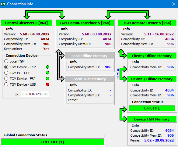
The Control Observer application is used for a complete monitoring of the TGMotion subsystem.
Here is an example of the connected TGZ+Motion device (using TCP protocol and IP address 192.168.128.188):
Fast service port (FSP)
This port serves as very fast and very easy port to setup connection to PC. To use it just connect directly the PC network card with the X12 connector. No switch or router is needed (and is not recommended). It is necessary to install special network driver called Winpcap or Npcap in Windows PC to use FSP. When selecting this type of connection, it takes some time to scan all the network adapters and check which one is connected to the TGZ+Motion device.
PLC programming
The source code of the TGMotion’s PLC is always compatible with all the TGMotion derivatives (Windows PC with real-time extension, TGMmini, TGZ+Motion, TGMcontroller and possible future systems). It means that the PLC can be programmed and tested e.g. on PC and then just recompiled for TGZ+Motion system. The PLC for TGZ+Motion must be written in C/C++ language.
Setup of the compiler environment
The PLC program can be compiled on any PC with Windows or Linux.
All needed applications are open source.
A cross compiler is necessary, it must be GCC compiler called gcc-arm-none-eabi.
The latest version can be downloaded from ARM website.
Choose the latest ZIP version and extract it to any folder.
The compiler must support at least C++17 standard/
The project for PLC uses the GNU standard makefile.
It is necessary to use the mingw32-make program to execute the makefile commands.
Themingw32-make can be downloaded e.g. from sourceforge.net and must be accessible from command line (e.g. by adding its path to the PATH system variable or using its filename together with the path on the command line).
Note that there is no need to have the GCC compiler in PATH.
The makefile has almost fixed structure, only the list of source/header files and the path to the compiler is necessary to edit or modify.
When the makefile is correct, the PLC can be created by command
executed in the directory where the makefile and source files are located.
Optionally use the full path of the mingw32-make.exe file, like
To rebuild the PLC, first clean the intermediate files by
and then build it by
Use the –j<number> option to compile it using more CPU cores, e.g.
Makefile example:
#path to TGM include files
TGM_PATH=..\include
#path to compiler
CC_PATH=..\..\gnu\gcc-arm-none-eabi\bin
#source files, must be in the same directory as this makefile
SOURCES=main.cpp \
DI_Capture.cpp \
Program_01.cpp \
Program_02.cpp \
Program_03.cpp \
Program_04.cpp \
Program_Ini.cpp \
Servo_Func.cpp \
$(TGM_PATH)\fmt\format.cpp
#used header file. these files are checked for dependencies
HEADERS=Definition.h \
DI_Capture.h \
PLC_Func.h \
Servo_Func.h \
stdafx.h \
User_Definitions.h \
User_Variables.h
USER_PATH=.\
#set the output filename
OUT_FILE_NAME=TGM_Controller_CAN_Tester
#===============================
#there is no need to change the rest of makefile
#compiler file names
CC=$(CC_PATH)\arm-none-eabi-g++.exe
OBJCOPY=$(CC_PATH)\arm-none-eabi-objcopy.exe
OBJDUMP=$(CC_PATH)\arm-none-eabi-objdump.exe
#stamper is special utility to mark the resulting PLC as for TGZ+Motion
STAMPER=tgm_bin_stamper.exe
OPTIMIZE=-O2
BSP_PATH=..\BSP
EXECUTABLE=$(OUT_FILE_NAME).elf
BIN_FILE=$(OUT_FILE_NAME).tgm.bin
STAMPED_FILE=$(OUT_FILE_NAME).tgm_controller
DUMP_FILE=$(OUT_FILE_NAME).elf.dbg
MAX_SERVO=64
MAX_DIO=16
MAX_INTERPOLATOR=3
SIZE_OSCILLOSCOPE=33554432
TGM_SETTINGS=-DMAX_SERVO_PROJECT_SETTINGS=$(MAX_SERVO) \
-DMAX_DIO_PROJECT_SETTINGS=$(MAX_DIO) \
-DMAX_INTERPOLATOR_PROJECT_SETTINGS=$(MAX_INTERPOLATOR) \
-DSIZE_OSCILLOSCOPE_MEMORY_PROJECT_SETTINGS=$(SIZE_OSCILLOSCOPE)
DEFINES=$(TGM_SETTINGS) \
-DFREERTOS \
-DZYNQ \
-DNDEBUG \
-DGLOBAL_TIMER_PRESCALER=1 \
-DNO_FILE_FUNCTIONS
CFLAGS=$(OPTIMIZE) -std=c++17 -I. -I$(BSP_PATH)\include -I$(TGM_PATH) \
-I$(USER_PATH) $(DEFINES) -g -Wall -Wextra -mcpu=cortex-a9 \
-mfpu=vfpv3 -mfloat-abi=hard -ffunction-sections -fdata-sections \
-Wno-unknown-pragmas
LDFLAGS=-g -mlittle-endian -Wl,-T -Wl,lscript.ld \
-Wl,--start-group,-lxil,-lgcc,-lc,-lstdc++,--end-group \
-L$(BSP_PATH)\lib -mcpu=cortex-a9 -mfpu=vfpv3 -mfloat-abi=hard \
-Wl,-build-id=none -specs=Xilinx.spec -Wl,--gc-sections
OBJECTS=$(SOURCES:.cpp=.o)
$(EXECUTABLE): $(OBJECTS) $(SOURCES) $(HEADERS) makefile
$(CC) $(OBJECTS) $(LIB_OBJECTS_C) $(LIB_OBJECTS_CPP) $(LIB_OBJECTS_ASM) \
-o $@ $(LDFLAGS)
cmd /C $(OBJDUMP) -C -x -S $(EXECUTABLE) >$(DUMP_FILE)
$(OBJCOPY) -O binary $(EXECUTABLE) $(BIN_FILE)
$(STAMPER) $(BIN_FILE) $(STAMPED_FILE) -oPLC -b0x07800000 -s0x00800000
%.o: %.cpp $(HEADERS) makefile | $(OBJDIR)
$(CC) -c $< $(CFLAGS) -o $@
all: $(SOURCES) $(HEADERS) $(EXECUTABLE) makefile
clean:
del /Q $(OBJECTS) $(EXECUTABLE) $(BIN_FILE) $(DUMP_FILE)
After creating executable .ELF file, the makefile creates a binary file and subsequently stamp it by a standalone utility tgm_bin_stamper.exe.
Ask TG Drives representatives for an example PLC program.
The project contains all the necessary files, compiler tools, linker script file, stamper program, BSP (board support package) and TGMotion public include files.
The file main.cpp contains the necessary access function GetProcAddress() which is used to get placement addresses of the main PLC functions: Program_Ini(), Program_01(), Program_02(), Program_03(), Program_04().
The function GetProcAddress() must be placed at startup address 0x07800000 and must not be optimized.
It also initializes the C standard library and all the dependencies like pointers to virtual functions and initialization of local and global variables.
See also the separate manual about PLC programing with TGMotion.
PLC programs priority and cycle time
The programs in the PLC runs with different priority. It is up to programmer to choose the right function for PLC tasks.
Program_04()has the highest priority and runs in the context of servo cycle function. It is called periodically at the interval given by Cycle_Time value in theTGM.INIfile (in microseconds). The allowed values are 100, 200, 250, 500, 1000, 2000, and then 3000, …, 10000 (in 1000 steps). It is very important that theProgram_04()does not last more than approx. half of the cycle time, otherwise TGMotion will not have chance to make its own calculations. The are no checks for too busyProgram_04()function, but the problem appears very quickly on the EtherCAT side of the system: the desired servo positions will not be updated and a following error arises in the servo amplifier itself. If it is absolutely necessary to do a heavy calculation in theProgram_04()function, the only solution is to increase the cycle time.-
Program_03()has a priority just one step below theProgram_04()and likewiseProgram_02()two steps belowProgram_04(). The programs are called repeatedly with the cycle time given in theTGM.INIfile. For example:
The values are given in microseconds and must be a multiple of 200.
The minimal allowed value is 200 µs.
To disable the given function completely, use value of zero.
TGZ+Motion checks the elapsed time in each function, and if less than 100 microseconds remain before the next function call, the actual call will not occur until the next 200-microsecond tick.
Thus TGZ+Motion can schedule other lower priority tasks (communication, etc.) and the Program_02() or Program_03() cannot overload the system.
3. Program_01() runs at the lowest priority possible within the system.
It means that other tasks, such as communication, Profinet handling, etc. will run with higher priority and will interrupt the Program_01() quite often.
On the other hand, the Program_01() get all the remaining CPU time, which is usually more than 90 %.
Additionally, the Program_01() is called as fast as possible (if the function is almost empty, the call interval is about 200 – 400 ns).
This conception allows to implement any time consuming calculations to the Program_01() without the fear of the system overload.
Note that there is no real-time behavior for the Program_01().
The cycle time in the TGM.INI file must be set to zero, no other value is allowed.
The Program_01() is always called – it cannot be disabled.
``` ini
[PLC_Configuration]
Cycle_Time_Program_01=0
```
The Control Observer’s System Timers window shows the elapsed time of various TGMotion’s tasks.
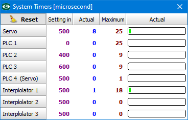
Note that the maximal elapsed time of the Program_01() (labeled as PLC 1) includes also the time of all the other tasks which interrupted the Program_01().
The similar thing happens for Program_02() which can be interrupted by Program_03() and the main servo cycle routine; and for Program_03(), interrupted by the main cycle function.
So the maximal value could be the sum of elapsed time of the PLC function and the tasks of higher priority.
The only exact time measurement is given for Program_04(), because it cannot be interrupted.
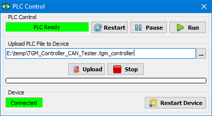
PLC start and autostart
In addition to Control Observer’s System Files window, there is a dedicated one for PLC programming – PLC Control.
Just set the correct PLC filename and Upload it to the TGZ+Motion.
The PLC is started by clicking the button [Run].
The Run PLC process performs the following sequence:
- Stops any running PLC and wait for all the Program_XX() functions to finish.
- Clear the PLC DATA memory.
- Clear (set to zero) all the digital outputs of connected I/O devices as well as servo drives. Set the mode of all servo drives to zero. The internal servo drive is detached from TGMotion.
- Set also the internal digital outputs to zero (if they are mapped to TGMotion).
- The main TGMotion’s loop is stopped and no additional EtherCAT messages are transmitted.
- The PLC is loaded to memory from SD card.
- The main loop starts again, the EtherCAT communication is active. The internal servo drive is attached back to the TGMotion (if set in the
TGM.INIfile). - The PLC initialization function,
Program_Ini()is called and when succeeds (returns 1), the periodic call ofProgram_XX()functions is established, i.e. the PLC is started.
The PLC can be started after the TGZ+Motion boots up.
Set the TGM.INI file entry
There is no synchronization between PLC start and EtherCAT communication.
Usually the PLC starts up faster than the EtherCAT communication.
The programmer must count with it and wait for example for EtherCAT state value (operational = 8) of the attached devices, or the requested number of found EtherCAT devices on the fieldbus (variable SYSTEM.MAIN.Found_Total_Number_Of_ECAT_Devices).
Internal servo type value in the TGM.INI file
To enable the internal TGZ servo of the TGZ+Motion device for the TGMotion subsystem, use the servo type 91:
[Servo_Configuration]
[Servo_Configuration]

Servo[00].Type=91
Servo[00].Node=1
Servo[00].Axis=1
Servo[00].Resolution=20

Servo[01].Type=91
Servo[01].Node=1
Servo[01].Axis=2
Servo[01].Resolution=20
The Node value is irrelevant and is ignored, but should be unique in the TGM.INI file.
The digital inputs and outputs are found in the SERVO[xx].DigitalIn and SERVO[xx].DigitalOut variables.
The table below shows the used inputs mapping.
It assumes the TGM.INI entries as given above (SERVO[00].Axis=1 and SERVO[01].Axis=2).
| Input pin | Axis | Appears at bit | Code example |
|---|---|---|---|
| DI1 | 1 | DigitalIn.0 | SERVO[00].DigitalIn & 0x001 |
| DI2 | 2 | DigitalIn.0 | SERVO[01].DigitalIn & 0x001 |
| DI3 | 1 | DigitalIn.1 | SERVO[00].DigitalIn & 0x002 |
| DI4 | 2 | DigitalIn.1 | SERVO[01].DigitalIn & 0x002 |
| DI5 | 1 | DigitalIn.2 | SERVO[00].DigitalIn & 0x004 |
| DI6 | 2 | DigitalIn.2 | SERVO[01].DigitalIn & 0x004 |
| DI7 | 1 | DigitalIn.3 | SERVO[00].DigitalIn & 0x008 |
| DI8 | 2 | DigitalIn.3 | SERVO[01].DigitalIn & 0x008 |
| EI1 | 1 | DigitalIn.8 | SERVO[00].DigitalIn & 0x100 |
| EI2 | 1 | DigitalIn.9 | SERVO[00].DigitalIn & 0x200 |
Outputs mapping is similar:
| Output pin | Axis | Used bit | Code for set | Code for clear |
|---|---|---|---|---|
| DO1 | 1 | DigitalOut.0 | SERVO[00].DigitalOut |= 0x01 | SERVO[00].DigitalOut &= ~0x01 |
| DO2 | 2 | DigitalOut.0 | SERVO[01].DigitalOut |= 0x01 | SERVO[01].DigitalOut &= ~0x01 |
| DO3 | 1 | DigitalOut.1 | SERVO[00].DigitalOut |= 0x02 | SERVO[00].DigitalOut &= ~0x03 |
| DO4 | 2 | DigitalOut.1 | SERVO[01].DigitalOut |= 0x02 | SERVO[01].DigitalOut &= ~0x03 |
| DO5 | 1 | DigitalOut.2 | SERVO[00].DigitalOut |= 0x04 | SERVO[00].DigitalOut &= ~0x04 |
| DO6 | 2 | DigitalOut.2 | SERVO[01].DigitalOut |= 0x04 | SERVO[01].DigitalOut &= ~0x04 |
Analog inputs values AN1, AN2 appears in the SERVO[00].AnalogIn and SERVO[01].AnalogIn variables.
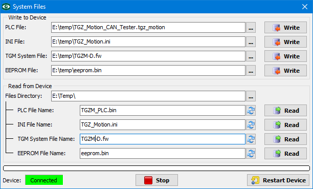
Firmware update
The firmware can be easily upgraded by Control Observer.
Just select the correct file in the TGM System File edit box and use the [Write] button.
Note that the file can be stored on the PC under any file name.
TGZ+Motion uses the correct file name when saving the file to the SD card.
After the file transfer, the device will be automatically restarted.
The updated firmware is stored to the SD card.
It is also possible to store the file directly to the SD card by PC, in that case the name must be TGZM-S.fw for single axis drive or TGZM-D.fw for double axis one and the file must be in the root directory of the card.
It could happen that a Device Offline error appears during the read back of the files from the device, especially when using FSP protocol. This usually means that used Ethernet adapter has not enough packet buffers (32 or more are recommended). The FSP protocol is designed for high performance adapters, namely the PCIe ones.
Profinet I/O device
Profinet I/O device is disabled by default.
Use the following settings in the TGM.INI file:
Each Profinet device is specified by its MAC address, IP address and device name.
These attributes should be unique within the Profinet network.
While the MAC address is fixed, the name and IP address can be set by a commissioning tool (TIA Portal, Proneta, etc.).
The default TGZ+Motion’s Profinet name is empty and IP address is set to 0.0.0.0.
The organization of the modules and slots is given by GSDML configuration file.
There are nine slots: 1 × DAP, 4 inputs slots (size 32, 64, 128 or 256 bytes) and 4 output slots (with the same sizes).
Each slot has an associated parameter which gives the data offset to PLC DATA memory.
This parameter can be set by the commissioning tool or by Profinet PLC program.
IP change
Be aware that changing the IP address of the Profinet device also changes that address of the service port X11. It means that a possible loss of TCP/UDP or other communication is possible. The solution is to use the same address for service protocols and for Profinet or use the FSP (X12) port for direct communication with the PC, independently to the Profinet network.
Modbus TCP
The Modbus TCP protocol is disabled by default.
To enable it, use the following TGM.INI configuration:
The PLC DATA memory is used for Modbus data store or receive. The Modbus register number is used as an offset to the memory. Because the register numbers count by 1, there is a value multiplier available with the default value of 4. Also a global offset can be used to shift the Modbus data in the DATA memory (default value 0). It is recommended that the global offset is divisible by 4. The final position of the Modbus data is calculated by:
final_offset_to_data_memory = global_offset + (multiplier × modbus_register_number)
The global offset and multiplier can be set also in the TGM.INI file. For example:
The following Modbus commands are supported:
| Command | Number |
|---|---|
| READ_COILS | 1 |
| READ_DISCRETE_INPUTS | 2 |
| READ_HOLDING_REGISTERS | 3 |
| READ_INPUT_REGISTERS | 4 |
| WRITE_SINGLE_REGISTER | 6 |
| WRITE_MULTIPLE_COILS | 15 |
| WRITE_MULTIPLE_REGISTERS | 16 |
Safe boot
TGZ-Motion normally boots from SD card.
In the case of faulty card or broken firmware, it is possible to start the device from internal flash memory.
Remove SD card and restart the system.
It takes a long time to start it without the SD card.
The system loads a default INI file contents with the IP address 192.168.1.188.
Use the FSP port if possible since no settings on the PC side is necessary.
Insert a new SD card formatted to FAT32 and upload all the necessary files: TGM.INI file and then TGZ+Motion firmware.
The device will be automatically restarted and should boot correctly from the SD card.
Use the TGZ GUI service program to correctly adjust the servo amplifier parameters like regulators, motor type, etc.
Save the parameters to the SD card.
The TGM.INI file is stored on the SD card in its natural text form, so it is also possible edit it directly by PC in the case of wrong settings. A restart of TGZ+Motion device is necessary after insertion of the SD card back to the device.