Device description
3D view


Connectors
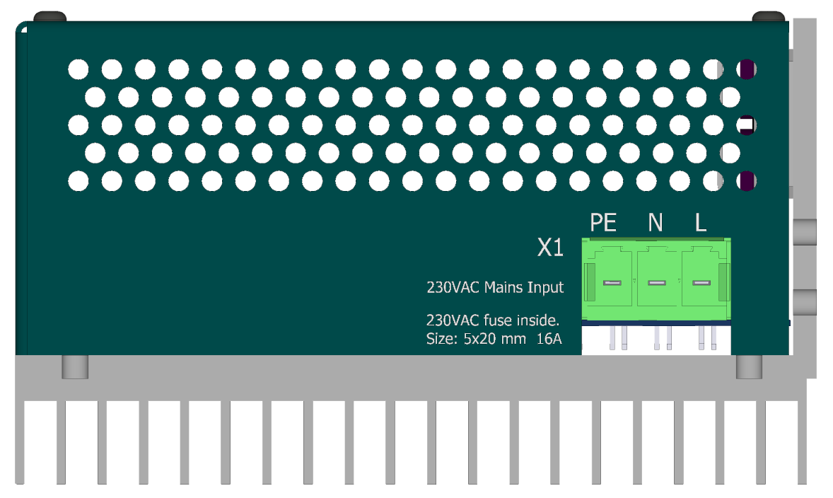
AC IN side view
-
X1 - Network connector

-
Phoenix PC 5/ 3-STCL1-7,62
pin # Marking Description AWG 1 PE protect earth 10 2 N Common 10 3 L Phase 10
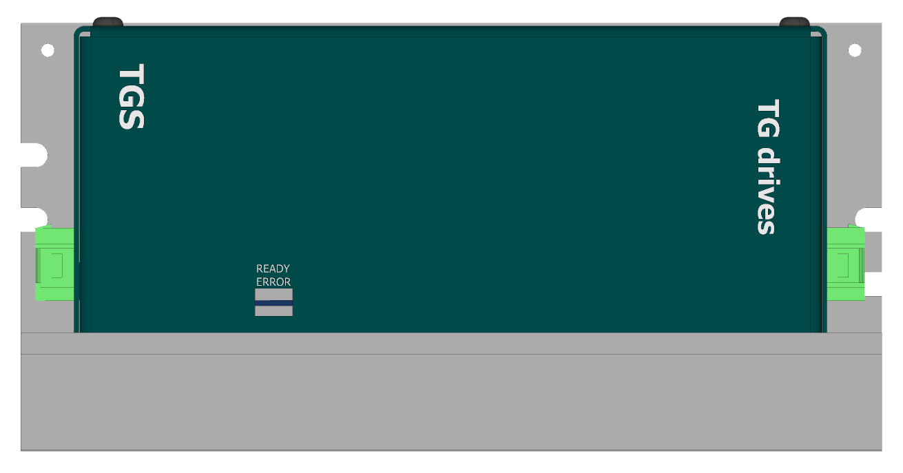
Status LEDs side view
-
status LEDs

-
LED diodes
LED diodes are mirroring status of the control output contacts. When the TGS is ready, and has no error status (overtemperature, overvoltage, undervoltage) the green LED is on. Otherwise the red LED is on.
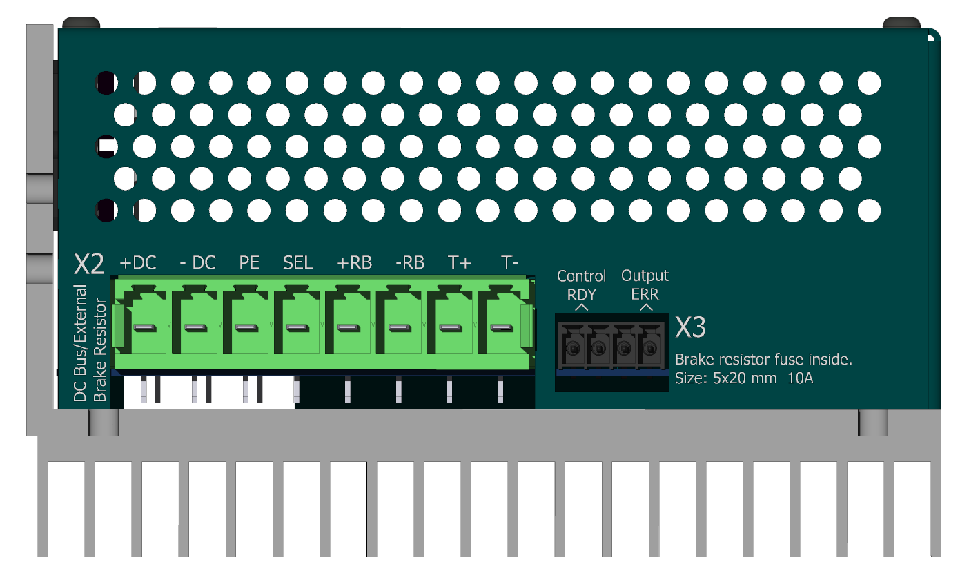
DC bus, control output side
-
X2 - DCbus out connector

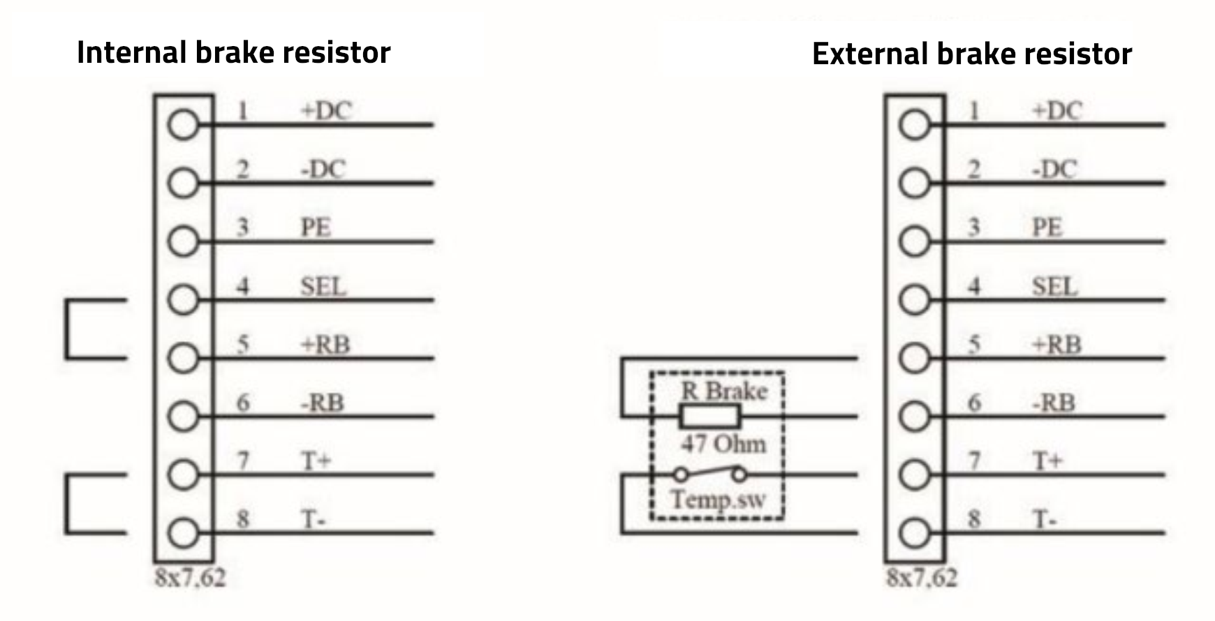
The X2 connector comes with jumper wires prepared for use with the internal chopper resistor.

If an external chopper (brake) resistor is used, the jumper wires must be removed and the resistor connected according to the schematic.
-
Phoenix PC 5/ 8-STCL1-7,62
pin # Marking Description AWG 1 + DC + DCbus supply 10 2 - DC - DCbus supply 10 3 PE protect earth 10 4 SEL regen. res. selection 10 5 + RB + Regen. resistor 10 6 - RB - Regen. resistor 10 7 + T + Thermistor 10 8 - T - Thermistor 10 -
X3 - Control output connector

-
Weidmüller BCZ 3.81/04/180 SN BK BX
pin # Marking Description AWG 1 RDY1 signal „Ready“ contact 1 16-24 2 RDY2 signal „Ready“ contact 2 16-24 3 ERR1 signal „Error“ contact 1 16-24 4 ERR2 signal „Error“ contact 2 16-24 The RDY and ERR outputs behave similar to relay contacts with a maximum allowable external power supply voltage of 28 VDC and a maximum load of 700 mA. They are most commonly used for signaling a power module fault to a higher-level system.
Contact closed Status Description RDY TGS OK The TGS module has not detected an error; voltage and temperatures are within acceptable limits. ERR TGS error The TGS module has detected one or more errors.