Device description
3D view


Connectors
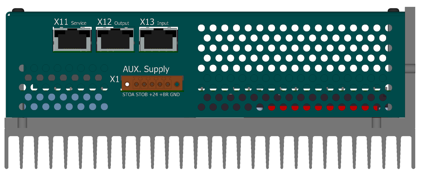
View of the ENET/ECAT side
-
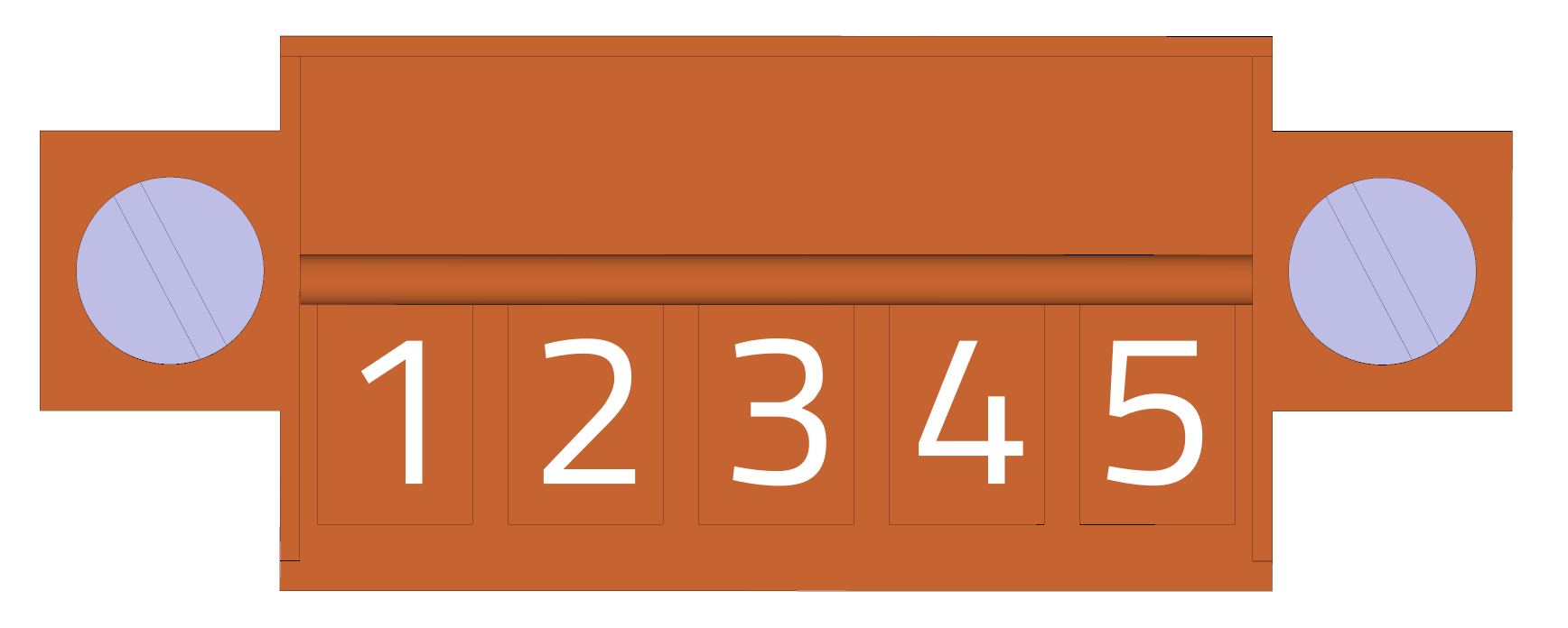
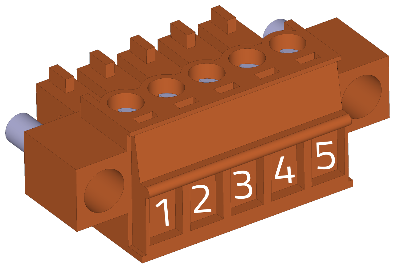
X1 - Control supply voltage
Housing back side view (wire side):
-
Weidmüller BCZ 3.81/05/180F SN OR BX
Pin č. Označení Popis Průřez 1 STO_A STO kanál A Max. 1,5 mm2 2 STO_B STO kanál B Max. 1,5 mm2 3 VCC +24V napájení řízení Max. 1,5 mm2 4 VCC_BR +24V napájení brzdy Max. 1,5 mm2 5 GND GND (0 V) Max. 1,5 mm2 EMI suppression
Please pay attention to the installation of the suppression toroidal core according to the instructions.
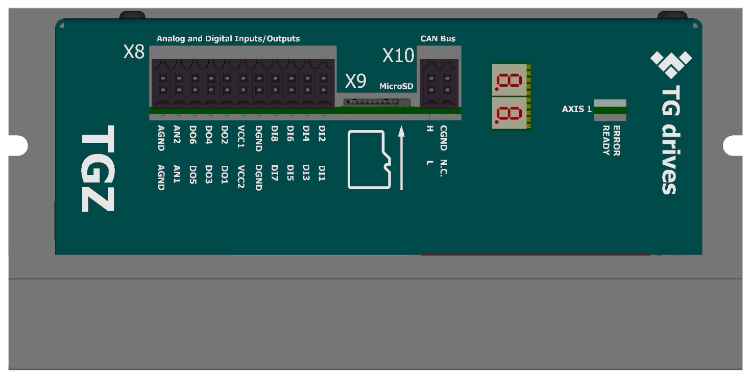
View of the CAN/IO/SD Side
-
X8 - Digital I/O, analog inputs
Cable side view
 3D view - cable side
  Front view (TGZ side)
Please see details about digital inputs DI1-8, digital outputs DO1-6 and analog inputs AI1-2 in the Common hardware section.
-
Weidmüller B2CF 3.50/22/180 SN OR BX
pin # Marking Description AWG 1 AGND Analog ground (internal) 16-25 2 AGND Analog ground (internal) 16-25 3 AIN2 Analog input no. 2 16-25 4 AIN1 Analog input no. 1 16-25 5 DO6 Digital output no. 6 16-25 6 DO5 Digital output no. 5 16-25 7 DO4 Digital output no. 4 16-25 8 DO3 Digital output no. 3 16-25 9 DO2 Digital output no. 2 16-25 10 DO1 Digital output no. 1 16-25 11 VCC DO2,4,6 Power for DO 2,4,6 (axis 2) 16-25 12 VCC DO1,3,5 Power for DO 1,3,5 (axis 1) 16-25 13 DGND Digital (iso) ground 16-25 14 DGND Digital (iso) ground 16-25 15 DI8 Digital input no. 8 16-25 16 DI7 Digital input no. 7 16-25 17 DI6 Digital input no. 6 16-25 18 DI5 Digital input no. 5 16-25 19 DI4 Digital input no. 4 16-25 20 DI3 Digital input no. 3 16-25 21 DI2 Digital input no. 2 16-25 22 DI1 Digital input no. 1 16-25 Warning
For proper operation of the DI(1-6) it is necessary to supply at least one of the VCC DO (pin 11 and 12). Inputs DI7,8 are independent of the DO VCC supply voltage and work correctly even without it.
-
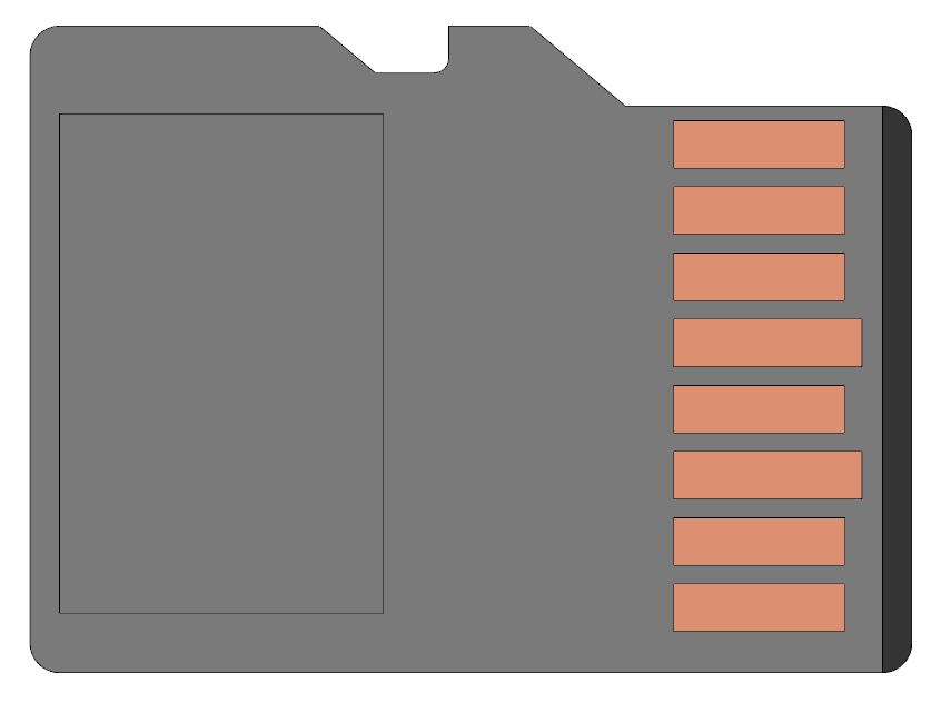
X9 - MicroSD card
-
Use a standard microSD card. The card is included with the TGZ servo amplifier. For more information, see SD cards.
-
X10 - CAN
Cable side view

3D view - cable side

Front view (TGZ side)

-
Weidmüller B2CF 3.50/04/180 SN OR BX
pin # Marking Description AWG 1 CANH CAN signal H 16-25 2 CANL CAN signal L 16-25 3 CANGND CAN isolated ground 16-25 4 NC No connection 16-25 For more information on the HW version of the CAN bus, see CAN bus.
-
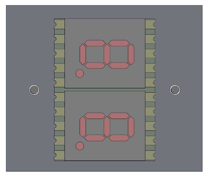
LED display
-
LED display indicates the status of the servoamplifier. See TGZ status indicators for detailed description.
-
status LEDs

-
LED diodes
LED color Status green Servo OK red Servo Error A complete description of the meaning of the status LEDs can be found here: TGZ status indicators
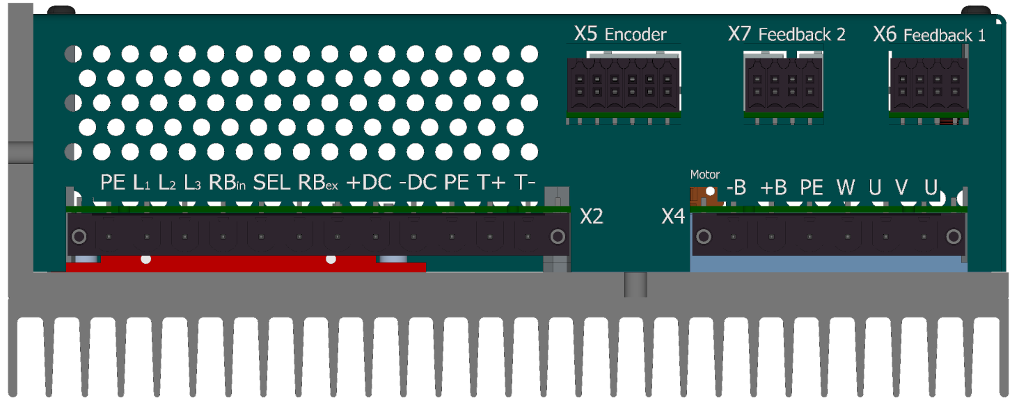
View of the FB/motor side
-
X5 - External encoder (FBE)
Cable side view

3D view - cable side

Front view (TGZ side)

-
Weidmüller B2CF 3.50/12/180 SN OR BX
pin # Endat 2.2/SSI/BISS Hiperface DSL Incremental encoder 1 GND GND GND 2 +5 V +5V +5V 3 ZERO- N.C. Z- 4 ZERO+ N.C. Z+ 5 N.C. FBSEL- N.C. 6 N.C. FBSEL+ N.C. 7 DATA- FBSEL- A- 8 DATA+ FBSEL+ A+ 9 CLK- N.C. B- 10 CLK+ N.C. B+ 11 GND DSL- GND 12 +12 V DSL+ +12 V For more information on external feedback, see FBE Feedback.
-
X6 - Feedback axis 1
Cable side view

3D view - cable side

Front view (TGZ side)

-
Weidmüller B2CF 3.50/08/180 SN OR BX
pin # Endat 2.2/SSI/BISS Hiperface DSL Incremental encoder 1 N.C. FBSEL- N.C. 2 N.C. FBSEL+ N.C. 3 DATA- FBSEL- A- 4 DATA+ FBSEL+ A+ 5 CLK- N.C. B- 6 CLK+ N.C. B+ 7 GND DSL- GND 8 +12 V DSL+ +12 V For more information regarding Feedback 1, please see Feedback FB1, FB2.
-
X7 - Feedback axis 2
Cable side view
3D view - cable side
Front view (TGZ side)
-
Weidmüller B2CF 3.50/08/180 SN OR BX
pin # Endat 2.2/SSI/BISS Hiperface DSL Incremental encoder 1 N.C. FBSEL- N.C. 2 N.C. FBSEL+ N.C. 3 DATA- FBSEL- A- 4 DATA+ FBSEL+ A+ 5 CLK- N.C. B- 6 CLK+ N.C. B+ 7 GND DSL- GND 8 +12 V DSL+ +12 V For more information regarding Feedback 2, please see Feedback FB1, FB2.
Note
Servoamplifier TGZ-S-400 is single axis version. The X7 connector is not normally connected.
-
X4 - Motor connector

Holding motor brake
For additional information on using the motor brake with the TGZ servo drive, see the Standard Brake section.
-
Weidmüller BLZ 7.62HP/06/180F
pin # Marking Description AWG 1 -B - Brake 13-24 2 +B + Brake 13-24 3 PE protect earth 13-24 4 W Phase W 13-24 5 V Phase V 13-24 6 U Phase U 13-24 Connector orientation
Pay attention to the correct orientation of the connector when connecting the wiring.
-
X2 - Power supply voltage

The X2 connector comes with jumper wires prepared for use with the internal chopper resistor.

If an external chopper (brake) resistor is used, the jumper wires must be removed and the resistor connected according to the schematic.
-
Weidmüller BLZ 7.62HP/12/180F
pin # Marking Description AWG 1 PE protect earth 11-24 2 L1 Phase 1 11-24 3 L2 Phase 2 11-24 4 L3 Phase 3 11-24 5 RBin Internal regen. resistor 11-24 6 SEL Regen. res. selection 11-24 7 RBex external regen. resistor 11-24 8 +DC + DCbus supply 11-24 9 -DC - DCbus supply 11-24 10 PE protect earth 11-24 11 T+ +Thermistor 11-24 12 T- -Thermistor 11-24