Codesys
Profile Position (PP) and Profile Velocity (PV) Modes
The TGZ servo drive supports additional positioning modes – profile position and profile velocity. In such cases, it uses its internal profile generator. The controller only sets the desired target position (or velocity), and the servo drive performs all the necessary calculations (acceleration/deceleration) to create a position or velocity profile. Communication between the controller and the device does not need to be in real-time. This process works identically for both EtherCAT and CAN field buses.
- Prepare the servo drive using the TGZ_GUI service program: set the
D-Moderegister to7: position PG mode. This setting is the same for both PP and PV modes.

- Depending on the fieldbus used, select
EtherCATorCANin theUseCANbussetting.
- If the fieldbus has been changed, save the parameters and restart the drive.
- Open the CODESYS development system and create a new Standard project.
- The Control Win device (soft real-time) is sufficient for PP and PV modes.
- Add the TGZ device description file (XML for EtherCAT, EDS for CANopen) to the device repository (if not yet done).
- Choose Install and select the correct description file.
- Right-click on Device (CODESYS Control Win V3 x64) and select Add Device.
- In the dialog that appears, select EtherCAT Master SoftMotion and click Add Device.
- Click on EtherCAT_Master_SoftMotion in the device tree. In the Add Device dialog, select the EtherCAT slave TGZ-Drives/TGZ/TGZ Drive V5 and add it to the project.
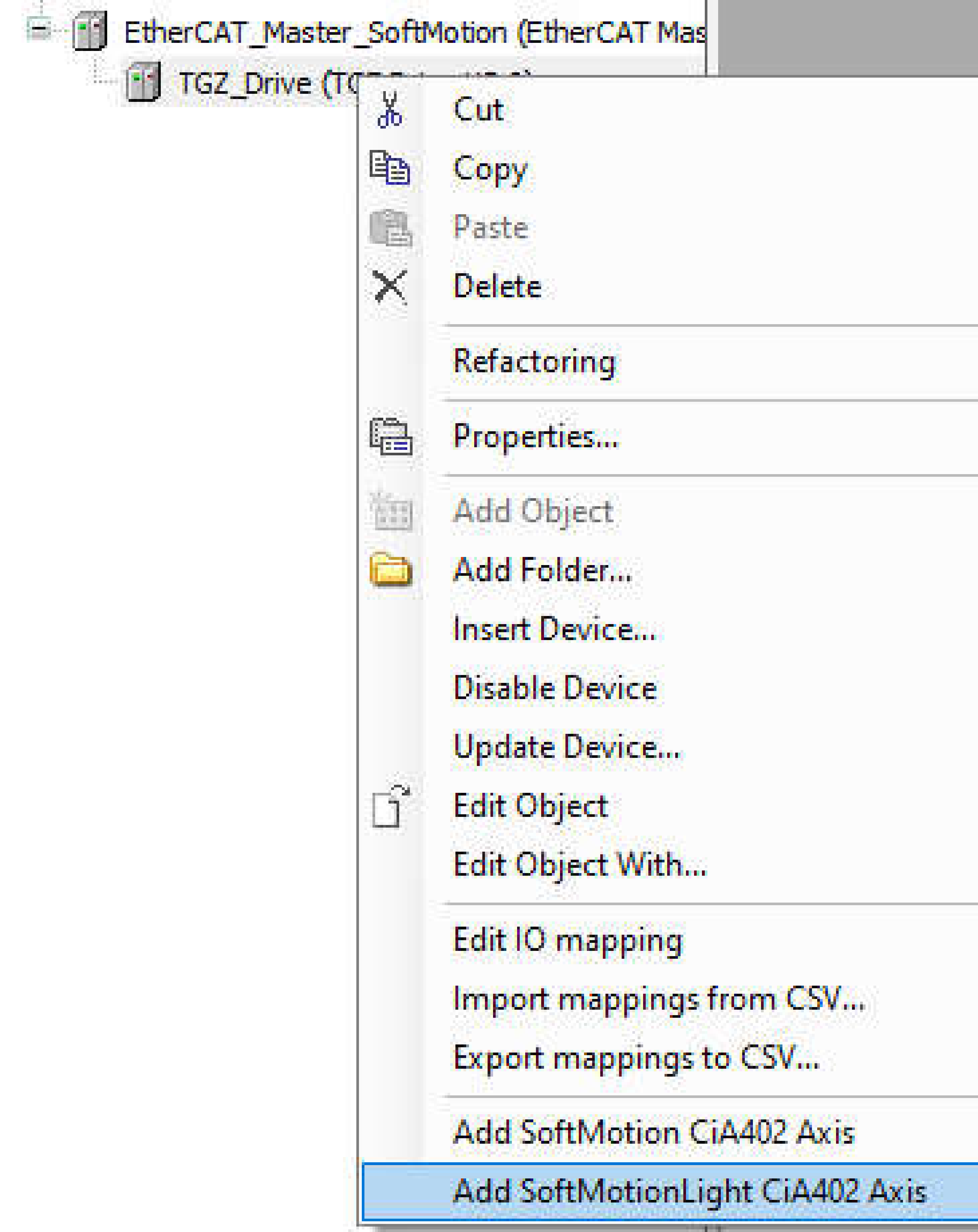
- Close the Add Device dialog and select TGZ Drive in the project device tree. Right-click and choose Add SoftMotionLight CiA402 Axis.
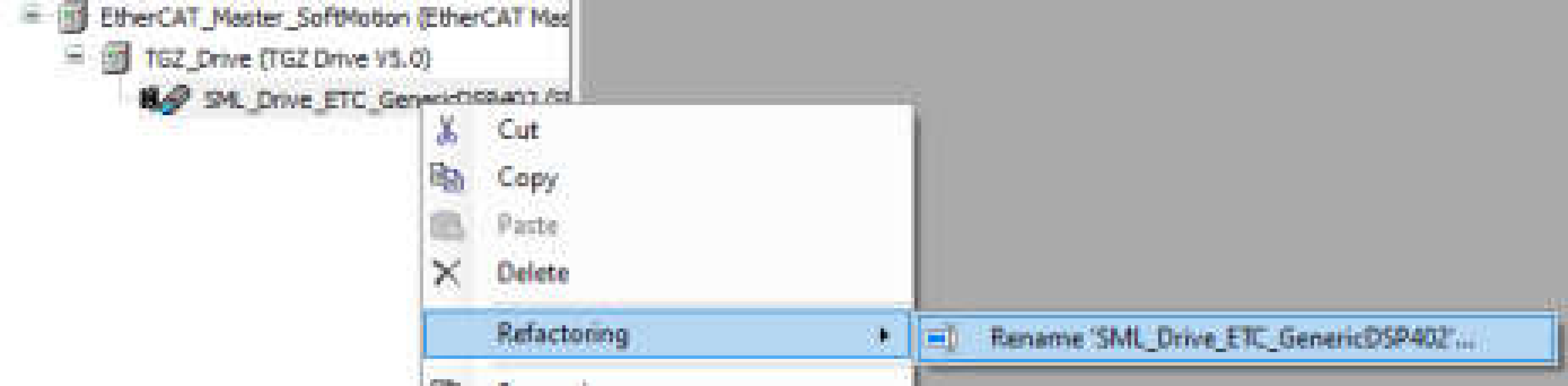
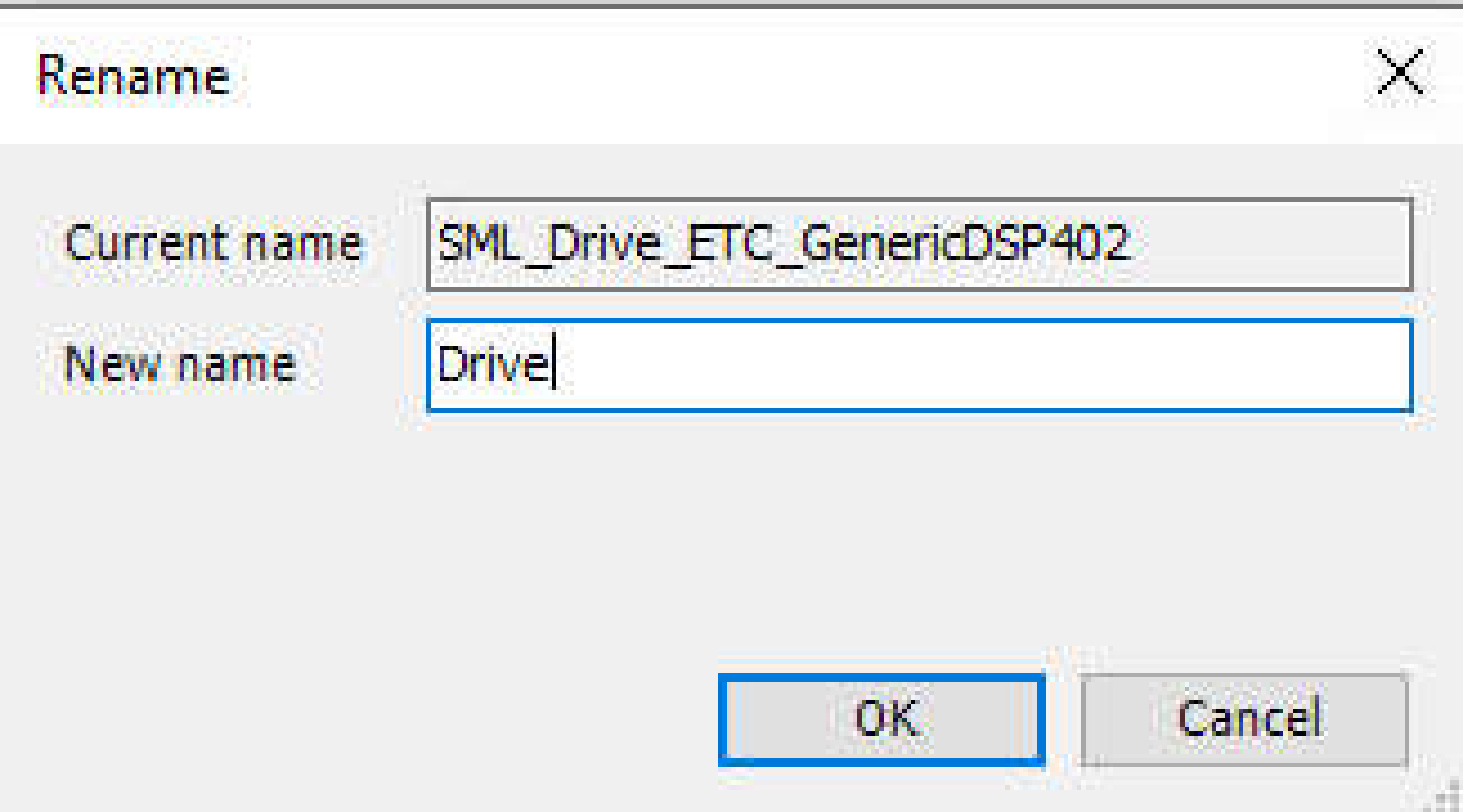
- Rename the added axis to Drive using the context menu Refactoring.
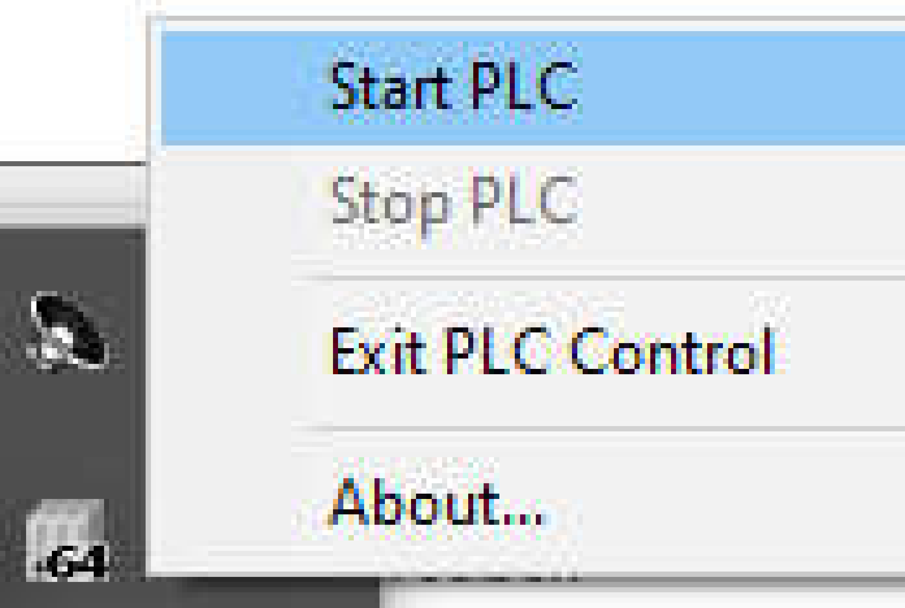
- Start Control Win PLC from the Windows system tray.
- Double-click on Device (CODESYS Control Win V3 x64) to open the communication settings window. Establish a connection by pressing Enter.
- Log in to the device using the username and password.
- After a successful login, the device icon should display a green light.

- Open the EtherCAT_Master_SoftMotion properties window by double-clicking on the item and select the network card used for the EtherCAT fieldbus by clicking the Select button.
- Check the Use LRW instead of LWR/LRD box.
- To assist the system in identifying the device on the fieldbus, set the correct device ID in the TGZ_Drive properties window. Enable Expert settings, then select Configured station alias (ADO 0x0012) and set the Value to the same number as in the
C-IDregister in the TGZ_GUI service program (5 in this example).
Group Common in TGZ_GUI

- In the TGZ_Drive properties window, select the Startup Parameters tab and change the value of SDO objects
6060and6860from8to1.
- The SoftMotion Lite can be easily tested and controlled using a prepared visualization named VISU_SML_StartupDrive. To use it, declare a helper variable in the PLC_PRG code of type
SML_StartupDriveand name it sml_visu, and also set a pointer to the same object.
PROGRAM PLC_PRG
VAR
    sml_visu: SML_StartupDrive;
    p_sml_visu : POINTER TO SML_StartupDrive := ADR(sml_visu);
END_VAR
p_sml_visu^(Axis := Drive);
 The statement
 p_sml_visu^(Axis := Drive) assigns the SoftMotion Lite Axis to the sml_visu variable. It could be run only once, e.g., in the StartDone event, but for simplicity, it is called periodically here. The sml_visu variable is needed in the visualization template (see below).
- Add a visualization to the application by right-clicking on the Application item and selecting Add Object/Visualization menu item.
- Keep the default name Visualization and click on the Add button.
- In the Visualization Toolbox window, select SML and then the VISU_SML_StartupDrive template.
- Drag and drop the template into the Visualization window and, in the following dialog box, assign m_Startup to the
sml_visuvariable created above.
- Position and resize the template as needed in the window.
-
Login and start the PLC. Now interact with the visualization. Enable bDriveStart, bRegulatorOn, and then Enable. Try absolute and relative movements. The MC_MoveVelocity_SML block changes the drive mode to PV. Stop the movement at any time using MC_Stop_SML. Read and Write parameters are used to access the internal members of the AXIS_REF_SML function block.
-
Observe the Control word, Status word, and Mode of operation in the TGZ_GUI.
Warning
Remember that the servo will position the motor, so be careful!