Connector description
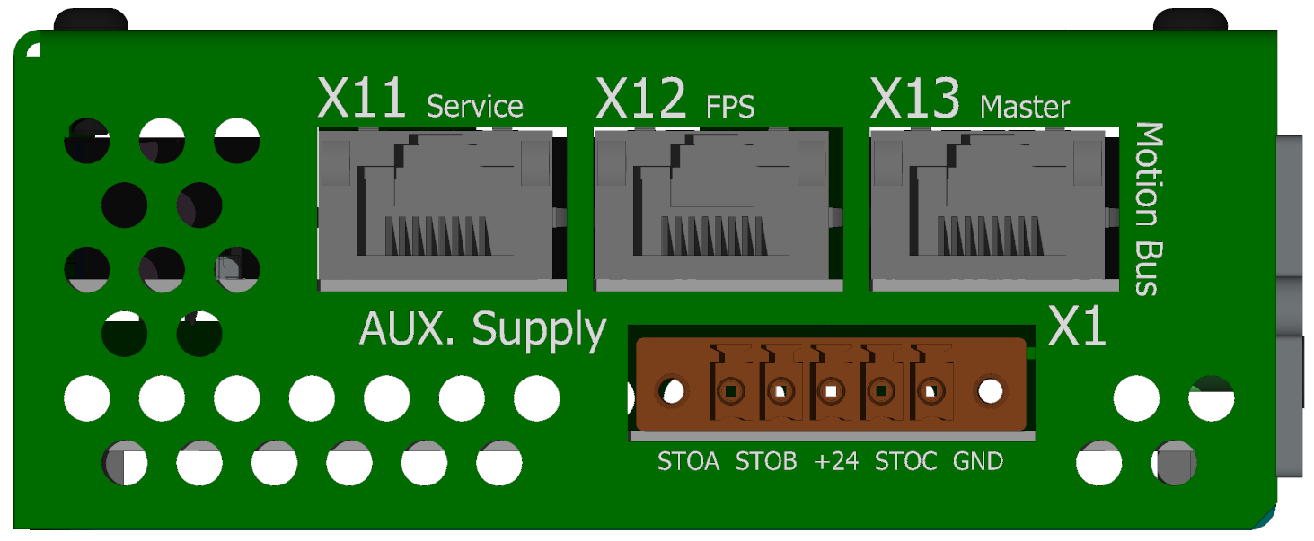
View of the ENET/ECAT side
-
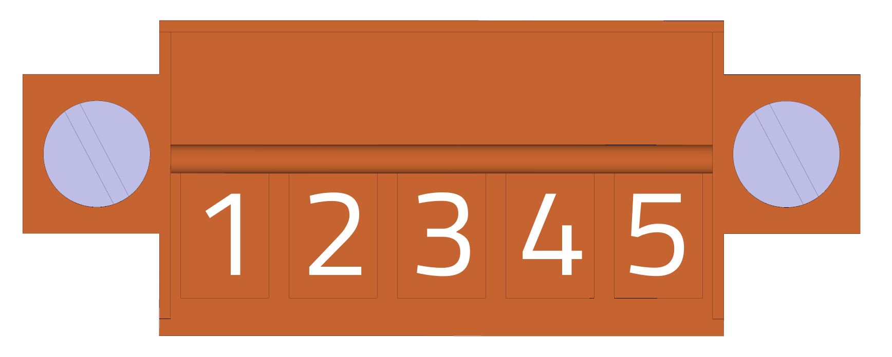
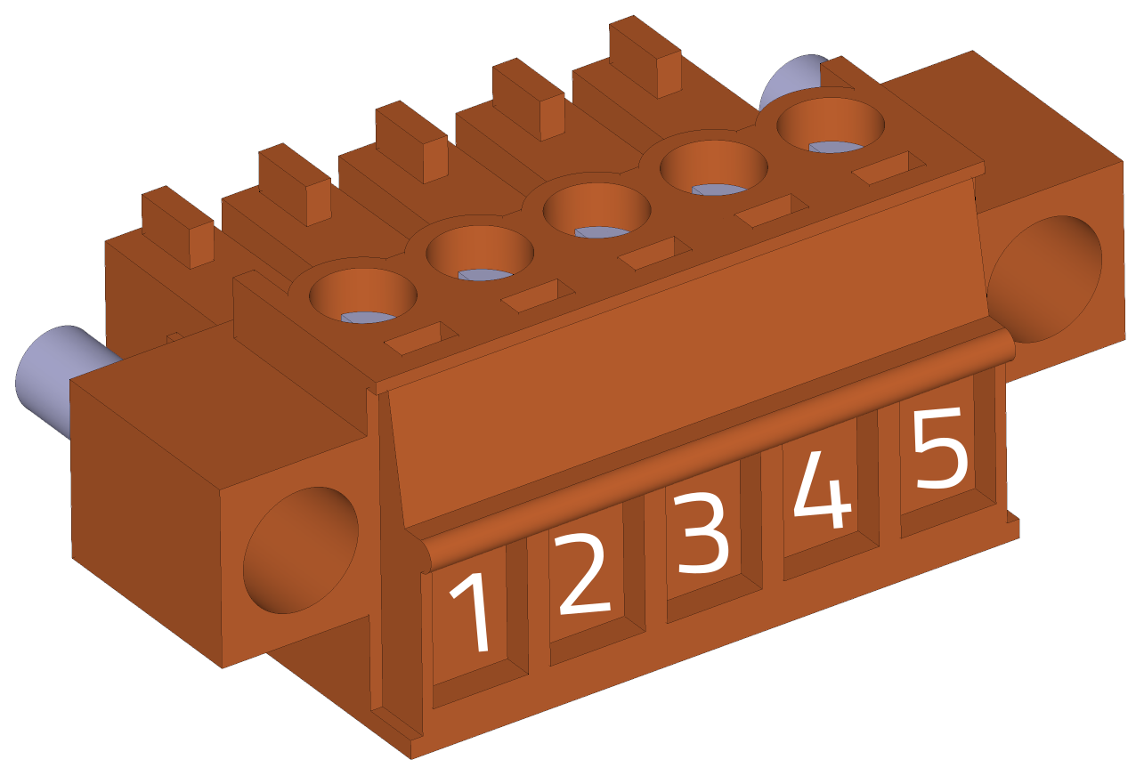
X1 - Control supply voltage
Housing back side view (wire side):
-
Weidmüller BCZ 3.81/05/180F SN OR BX
pin # Marking Description AWG 1 EI1 Extension input 1 16-24 2 EI2 Extension input 2 16-24 3 VCC +24V power 16-24 4 N.C. No connect 16-24 5 GND GND (0 V) 16-24 EIx
Extended inputs work as standard digital inputs 0 – 24 V. See also IO mapping).
-
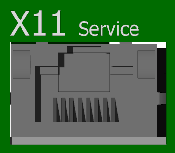
X11 - TGMotion service connector
-
RJ45
It is used for connecting the TGMotion system (TCP or UDP protocol) by Control Observer and other user applications. Additional supported protocols are Modbus/TCP and Profinet IO (see below).
-
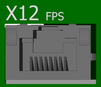
X12 - FSP port
-
RJ45
This port is used for so called Fast Service Port. Serves for very fast peer-to-peer connection between TGMcontroller and PC. Special custom raw protocol is used. The PC must install Winpcap or Npcap driver. No setting is necessary, the communication DLL finds the correct PC network adapter. For best performance, use the built-in or PCIe NIC adapters. The USB-Ethernet adapters can be also used, but suffer of worse performance. Some low cost USB to Ethernet adapters don’t work at all with the FSP protocol. The adapter must have space for at least 32 packets at one time.
-
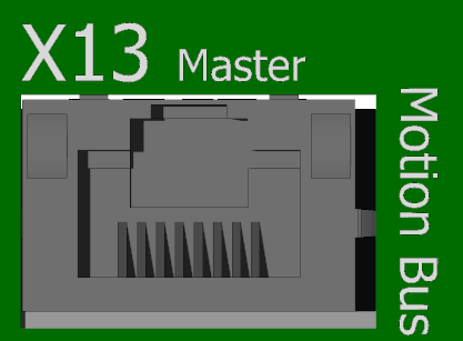
X13 - EtherCAT master
-
RJ45
EtherCAT master connector – use this port for connecting the EtherCAT devices in the EtherCAT fieldbus. No setting is necessary. The port is capable of 100 Mbit or 1 Gbit speeds, depending of the first connected device. There are a few 1 Gbit EtherCAT devices available, e.g. TGZ servo drives or several EtherCAT bridges from other manufacturers. If using the 1 Gbit fieldbus, all the devices in the chain must be using the 1 Gbit speed.
View of the CAN/IO/SD Side
-
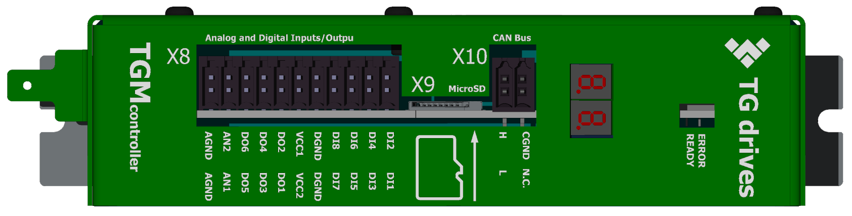
X8 - Digital I/O, analog inputs
Cable side view
 3D view - cable side
  Front view (TGZ side)
-
Weidmüller BCZ 3.81/22/180 SN OR BX
pin # Marking Description AWG 1 AGND Analog ground (internal) 16-25 2 AGND Analog ground (internal) 16-25 3 AIN2 Analog input no. 2 16-25 4 AIN1 Analog input no. 1 16-25 5 DO6 Digital output no. 6 16-25 6 DO5 Digital output no. 5 16-25 7 DO4 Digital output no. 4 16-25 8 DO3 Digital output no. 3 16-25 9 DO2 Digital output no. 2 16-25 10 DO1 Digital output no. 1 16-25 11 VCC DO2,4,6 Power for DO 2,4,6 (axis 2) 16-25 12 VCC DO1,3,5 Power for DO 1,3,5 (axis 1) 16-25 13 DGND Digital (iso) ground 16-25 14 DGND Digital (iso) ground 16-25 15 DI8 Digital input no. 8 16-25 16 DI7 Digital input no. 7 16-25 17 DI6 Digital input no. 6 16-25 18 DI5 Digital input no. 5 16-25 19 DI4 Digital input no. 4 16-25 20 DI3 Digital input no. 3 16-25 21 DI2 Digital input no. 2 16-25 22 DI1 Digital input no. 1 16-25 Warning
For proper operation of the DI(1-6) it is necessary to supply at least one of the VCC DO (pin 11 and 12). Inputs DI7,8 are independent of the DO VCC supply voltage and work correctly even without it.
-
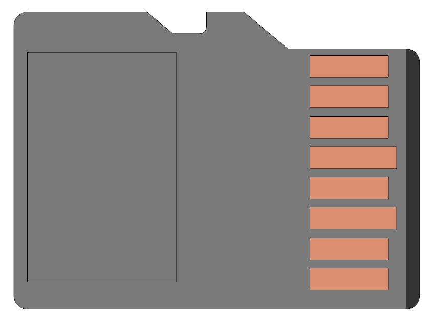
X9 - MicroSD card
-
Use a standard microSD card.
-
X10 - CAN
Cable side view

3D view - cable side

Front view (TGZ side)

-
Weidmüller BCZ 3.81/04/180 SN OR BX
pin # Marking Description AWG 1 CANH CAN signal H 16-25 2 CANL CAN signal L 16-25 3 CANGND CAN isolated ground 16-25 4 NC No connection 16-25 -
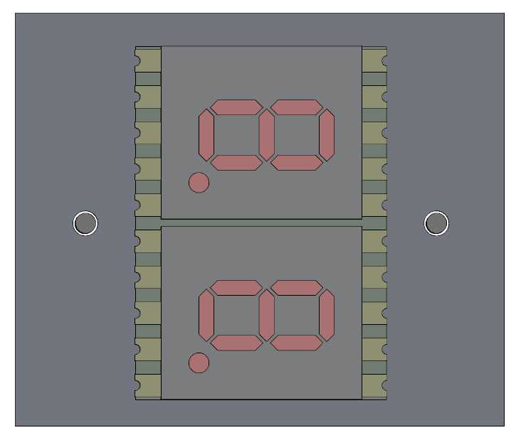
LED display
-
The LED display shows the device IP address during startup. The text “IP” is followed by numbers. Since the numbers can have up to 3 digits, each complete number is separated by a dot. For example to display the number “
192”, first a single “1” is displayed (without a dot) and then “92.” (with the dot). Complex IP addresses like192.168.128.179can be displayed in this way. -
status LEDs

-
There are four additional LED diodes labeled as ERROR (red color) and READY (green color) for two axes. The READY shows that this particular axis is enabled in the
TGM.INIfile, on the other hand ERROR means the axis is not mapped to TGMotion by theTGM.INIfile. See also IO mapping about the entries in theTGM.INIfile.
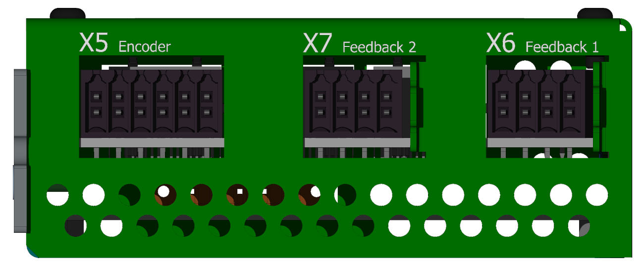
Feedback side view
-
X5 - External encoder (FBE)
Cable side view

3D view - cable side

Front view (TGZ side)

-
Weidmüller BCZ 3.81/12/180 SN OR BX
pin # Incremental encoder 1 GND 2 +5V 3 Z- 4 Z+ 5 N.C. 6 N.C. 7 A- 8 A+ 9 B- 10 B+ 11 GND 12 +12 V The X5 connector is used for an incremental encoder (IRC).
-
X6 - Feedback axis 1
Cable side view

3D view - cable side

Front view (TGZ side)

-
Weidmüller BCZ 3.81/08/180 SN OR BX
pin # Endat 2.2/SSI/BISS Hiperface DSL 1 N.C. FBSEL- 2 N.C. FBSEL+ 3 DATA- FBSEL- 4 DATA+ FBSEL+ 5 CLK- N.C. 6 CLK+ N.C. 7 GND DSL- 8 +12 V DSL+ FB1
The X6 connector supports either Hiperface DSL feedback or EnDAT 2.2 standard. The type of the used feedback communication standard is given in the
TGM.INIfile:Servo[xx].FeedbackType=1is for DSL andServo[xx].FeedbackType=2is for EnDAT. -
X7 - Feedback axis 2
Cable side view
3D view - cable side
Front view (TGZ side)
-
Weidmüller BCZ 3.81/08/180 SN OR BX
pin # Hiperface DSL SSI 1 FBSEL- N.C. 2 FBSEL+ N.C. 3 FBSEL- DATA- 4 FBSEL+ DATA+ 5 N.C. CLK- 6 N.C. CLK+ 7 DSL- GND 8 DSL+ +12 V The X7 connector can be used with DSL or SSI feedback. Use the following settings in the
TGM.INI:Servo[xx].FeedbackType=1for the DSL andServo[xx].FeedbackType=3for the SSI.