Virtual PLC
Virtual PLC description
The Virtual PLC module executes a PLC program written by the user.
It performs calculations, controls servo drives, reads and sets input and output values and takes care of communication with other peripherals only via shared memory.
The virtual PLC is periodically called from TG Motion at the interval set in Cycle_Time.
The Cycle_Time size is defined in the TGMotion4xx.ini file.
The advantage of the Virtual PLC is its speed because it runs directly in the CPU machine code.
Warning
The Servo and I/O groups unify the control interface for different types of servo drives and I/O units. The same PLC code can be applied to different servo drives or I/O units. Servo drives or I/O units can also be changed operationally without rewriting the PLC code.
Making of a PLC
The PLC program can be created in a general development environment, e.g. Visual Studio, Delphi.
The programming language can be C, C++ and Pascal.
In the development environment, you need to create a *.tgm file, which must publish just six functions with names:
Program_01, Program_02, Program_03, Program_04, Program_05 and Program_Ini.
The names given are mandatory, including the case of the letters.
The *.tgm program module must not be linked with any external modules or DLLs, all program functionality (functions, subroutines, ...) must be created by the programmer directly in the module.
Any Windows API functions must not be called, dynamic memory allocation (malloc function, etc.) is forbidden.
Warning
All the following source code examples are for the C/C++ programming language.
Required PLC algorithm
The general PLC algorithm requires the following sequence of execution, in the exact order listed:
-
Reading entries In the first phase, it is necessary to read the register values of all required inputs. This includes the positions and states of the servo drives as well as the values of the digital and analog inputs (see Servo structure and I/O structure).
-
Value processing and calculations The next step is to process the read values and calculate new values (desired positions of actuators and values of digital and analogue outputs).
-
Setting Outputs The last step is to send the desired positions to the actuators and set the digital and analogue values outputs by writing values to the appropriate registers.
Communication with PLC
Other TG Motion components and user applications running under Windows can communicate with the PLC using the shared memory TGM_Data.
TG Motion does not interfere with it in any way and does not rewrite its content.
The structure of this memory and its use is fully in the PLC programmer's control.
The size of the shared memory TGM_Data is usually 524 288 bytes.
The actual memory size is contained in the TGM_System.HEADER.Mem_Size_Data register.
The memory can contain user registers, cam data, etc.
It is most often used by visualization applications running under Windows.
Functions PLC
General description of functions
The programming module of the Virtual PLC has 6 functions available.
These differ in their execution priority and the requirement for their complete execution within one Cycle_Time.
For correct and error-free operation of the Virtual PLC it is necessary that the required code is placed in the appropriate function (see below):
- Program_Ini( ) - function called only once when starting the PLC.
- Program_01( ) - lowest priority, selectable calling period.
- Program_02( ) - lower priority, selectable calling period.
- Program_03( ) - higher priority, selectable calling period.
- Program_04( ) - highest priority, it is called every Cycle_Time.
- Program_05( ) - highest priority, called synchronously with the interpolator position calculation (multiple times during one Cycle_Time)
Warning
All functions must be implemented, some do not need to contain executable code. It is always necessary to provide the return value of the function. See code example of the Program_02 function.
PLC_DATA structure
The structure is used for communication between TG Motion and PLC.
TG Motion creates 6 instances of the PLC_DATA structure.
Each of the 6 functions (Program_01 - Program_05, Program_Ini) has just 1 parameter, a pointer to the PLC_DATA structure.
When a function is called, TG Motion passes it a pointer to the structure instance that belongs to it.
The PLC_DATA structure contains pointers to shared memories and pointers to TG Motion's internal diagnostic functions.
Definition of diagnostic functions
#ifdef __cplusplus
extern "C" {
#endif
typedef int _cdecl RTWPRINTF_STRING(LPCWSTR strText); // dump the string to the console
typedef int _cdecl RTWPRINTF_LONG(LPCWSTR strFormat, long lVal);
// dump the value of the lVal variable to the console
typedef int __cdecl SWPRINTF(wchar_t *buffer, size_t sizeOfBuffer, const wchar_t *strFormat, ...);
// writing formatted text to the buffer string
typedef void __cdecl SLEEPFT(PLARGE_INTEGER Pause); // waiting
typedef BOOL __cdecl CAN_TRANSMIT(ULONG Number, ULONG Id, ULONG Dlc, PUCHAR Tx_Data ); // reserved
typedef BOOL __cdecl CAN_TRANSMITREMOTE(ULONG Number, ULONG Id, ULONG Dlc, PUCHAR Tx_Data); // reserved
typedef int __cdecl RTWPRINTF_EX(int severity, const wchar_t *strFormat, ...);
// dump formatted text to the console
#ifdef __cplusplus
};
#endif
Pointers to diagnostic functions
typedef struct _PLC_IMPORT_FUNCTIONS
{
RTWPRINTF_STRING *pRtWprintf_String;
RTWPRINTF_LONG *pRtWprintf_Long;
SWPRINTF *pswprintf;
SLEEPFT *pSleepFt;
CAN_TRANSMIT *pCAN_Transmit;
CAN_TRANSMITREMOTE *pCAN_TransmitRemote;
RTWPRINTF_EX *pRtWprintf_Ex;
} PLC_IMPORT_FUNCTIONS;
Custom PLC_DATA structure
typedef struct _PLC_DATA
{
size_t structSize; // structure size in bytes
void *PSystem_Memory; // pointer to shared memory TGM_System
void *PData_Memory; // pointer to shared memory TGM_Data
void *POsc_Memory; // pointer to shared memory TGM_Oscilloscope
void *PCam_Memory; // pointer to shared memory TGM_Cam_Profile
void *PServo_Memory; // pointer to shared memory TGM_Servo
void *PDio_Memory; // pointer to shared memory TGM_Dio
void *PInterpolator_Memory; // pointer to shared memory TGM_Interpolator
void *Pointer_interpolator_params; // pointer to shared memory TGM_InterpolatorWriteMemory
void *Pointer_interpolator_get_position; // pointer to shared memory TGM_InterpolatorReadMemory
void *PCNCEx; // pointer to shared memory TGM_CNCEX
void *PGCode; // pointer to shared memory TGM_GCODE
void *PReserve3_Memory; // reserved
void *PReserve4_Memory; // reserved
void *PReserve5_Memory; // reserved
void *PReciveDataCan1; // reserved
void *PReciveDataCan2; // reserved
PLC_IMPORT_FUNCTIONS functions; // structure with pointers to diagnostic functions
} PLC_DATA, *PPLC_DATA;
Functions by priority
In this chapter, the functions are ordered from lowest priority to highest priority.
The Program_Ini function is not a priority in the true sense of the word.
This function is called only once when starting the Virtual PLC.
Program_Ini
Declaration: long Program_Ini(PLC_DATA *pData)
This function is called only once, when the Virtual PLC is started.
It is used mainly for initializing the Virtual PLC variables.
The executive code of the Program_Ini function must not be empty.
There is no limit to the length of time that a person may serve.
Warning
When starting the Virtual PLC (in the body of the Program_Ini function) it is advisable to check the PLC and TG Motion versions.
Function return values
- 0 - error (PLC start-up stops; the user must solve the error and restart the PLC).
- 1 - the function ended without errors.
Warning
When loading the Virtual PLC, the values of global variables are not initialized, the constructors of global objects are not called.
The initialization must be done in the Program_Ini function.
Source code sample
long Program_Ini(PLC_DATA *pData)
{
if (pData == NULL || pData->structSize != sizeof(PLC_DATA)) return 0;
if (pData->functions.pRtWprintf_Long == NULL) return 0;
if (pData->functions.pRtWprintf_String == NULL) return 0;
if (pData->functions.pswprintf == NULL) return 0;
if (pData->functions.pSleepFt == NULL) return 0;
if (pHeader->Compatibility_Id != ID_COMPATIBILITY)
{
pData->functions.pswprintf(info_ini, SIZE_INFO, L "Error start of PLC PLC_COMPABILITY_ID = %d
TGM_COMPATIBILITY_ID = %d \n", ID_COMPATIBILITY, pHeader->Compatibility_Id);
pData->functions.pRtWprintf_String(info_ini);
return 0;
}
//****************************************** Update PLC Version ***********************************
Version_PLC = Get_Version(PLC_VERSION);
//*************************************************************************************************
return 1;
}
Program_01
Declaration: long Program_01(PLC_DATA *pData)
The function is called from TG Motion with the period specified in the TGMotion4xx.ini configuration file.
The period is defined by the Cycle_Time_Program_01 item, its value ranges from 100 to 10000 μs (the upper limit is not limited).
The length of the function execution should not exceed 20 % of Cycle_Time_Program_01 to leave time for the execution of Program_02 and Program_03 functions.
This function is most often used for basic servicing of devices that do not need to be serviced regularly every Cycle_Time.
Function Program_01 has the lowest priority and can be interrupted at any time by functions Program_02, Program_03, Program_04 and Program_05.
Program_02
Declaration: long Program_02(PLC_DATA *pData)
The function is called from TG Motion with the period specified in the TGMotion4xx.ini configuration file.
The period is defined by the Cycle_Time_Program_02 item, its value ranges from 100 to 10000 μs (the upper limit is not limited).
The duration of the function execution should not exceed 20 % of Cycle_Time_Program_02 to leave time for the execution of the Program_01 and Program_03 functions.
This function is usually implemented as an empty function.
The Program_02 function has low priority and can be interrupted at any time by the Program_03, Program_04, and Program_05 functions.
Source code sample
Program_03
Declaration: long Program_03(PLC_DATA *pData)
The function is called from TG Motion with the period specified in the TGMotion4xx.ini configuration file.
The period is defined by the Cycle_Time_Program_03 item, its value ranges from 100 to 10000 μs (the upper limit is not limited).
The length of the function execution should not exceed 20 % of Cycle_Time_Program_03 to leave time for the execution of the Program_01 and Program_02 functions.
This function is usually implemented as an empty function.
The Program_03 function has low priority and can be interrupted at any time by the Program_04 and Program_05 functions.
Source code sample
Program_04
Declaration: long Program_04(PLC_DATA *pData)
The function is called from TG Motion synchronously with the communication within the Cycle_Time, i.e. once during each Cycle_Time.
It is defined in the TGMotion4xx.ini file by the Cycle_Time item (250 μs, 500 μs, 1000 μs).
The Program_04 function is most often used to modify the desired position of servo drives and to operate I/O units.
It has the highest priority (as does the Program_05 function) and always executes in its entirety without interruption.
The execution time of the Program_04 function must not exceed 10 % of Cycle_Time to ensure timing accuracy of communication with servo drives and I/O units.
Warning
The function SleepFt must not be called in the function Program_04
Program_05
Declaration: long Program_05(PLC_DATA *pData)
The function is called from TG Motion synchronously with the interpolator, i.e. several times during each Cycle_Time.
The Program_05 function is most often used to modify the position calculated by the interpolator module.
It has the highest priority (as does the Program_04 function) and always executes in its entirety without interruption.
The execution time of the Program_05 function must not exceed 10 μs to ensure timing accuracy of communication with servo drives and I/O units.
Warning
The function SleepFt must not be called in the function Program_05
Timing sequence of function calls
Cycle_Time = 250 μs
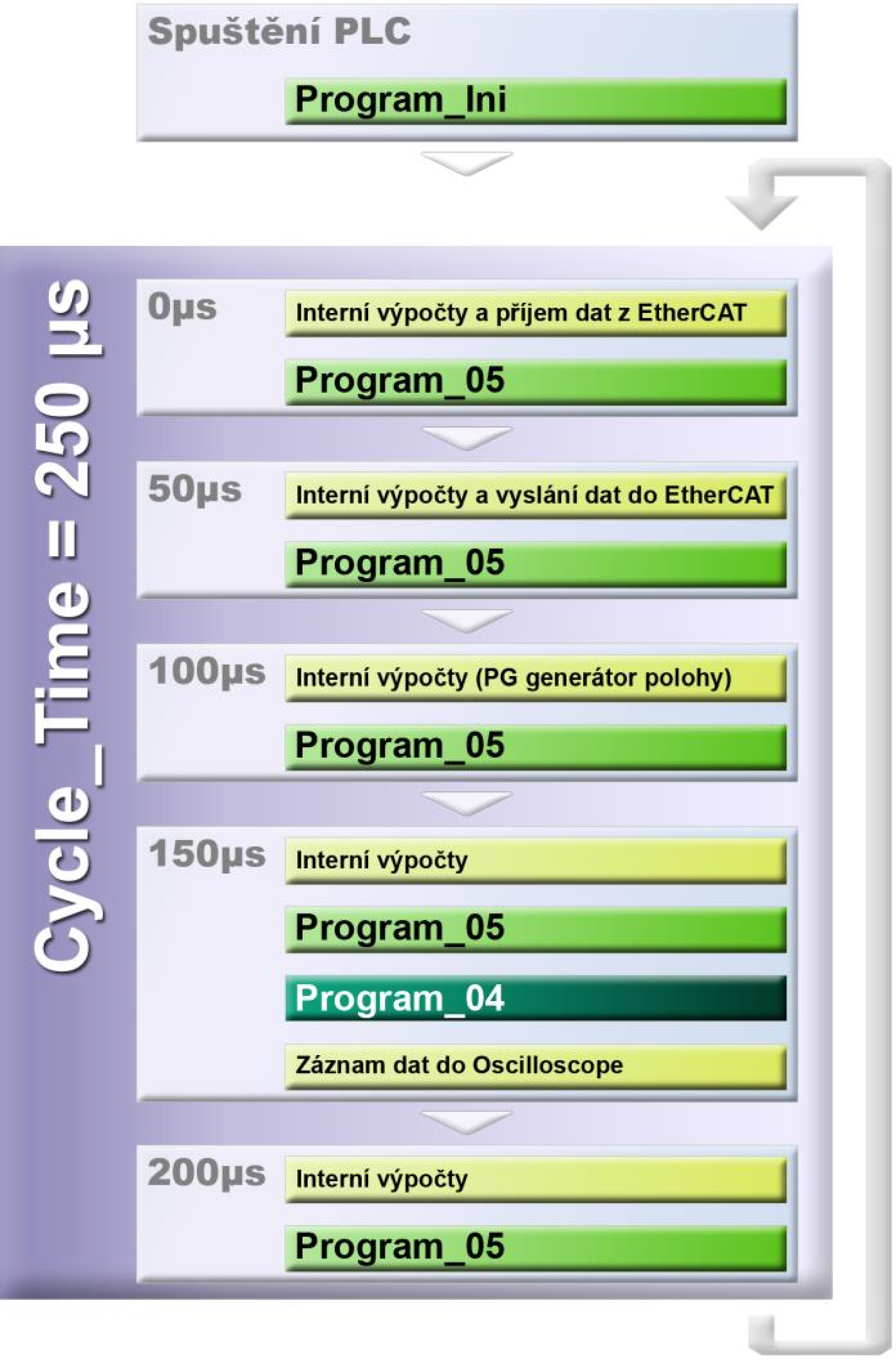
After starting the PLC and successful execution of the Program_Ini function, a cyclic loop call lasting 250 μs is started.
It is evenly divided into 5 equal time periods called regularly every 50 μs.
-
Time 0 μs The necessary internal calculations are performed and the EtherCAT data is received. The function Program_05 is then called and the entire function is executed without interruption.
-
Time 50 μs The necessary internal calculations are performed and the data is sent to EtherCAT. The function Program_05 is then called and the entire function is executed without interruption.
-
Time 100 μs The necessary internal calculations are performed and the desired position data is calculated using PG generators. Then willfunction Program_05, which will be executed without interruption.
-
Time 150 μs The necessary internal calculations are performed and the function Program_05 is called, which is executed without interruption. Then the function Program_04 is called, which is also executed without interruption. Finally, all the data needed for the Oscilloscope is recorded.
-
Time 200 μs The necessary internal calculations are performed and the function Program_05 is called, which is executed without interruption.
If the computing capacity is free during any cycle, the Program_01, Program_02 and Program_03 functions are operated if necessary.
Cycle_Time = 500 μs

After starting the PLC and successful execution of the Program_Ini function, a cyclic loop call lasting 500 μs is started.
It is evenly divided into 5 equal time periods called regularly every 100 μs.
-
Time 0 μs The necessary internal calculations are performed and the EtherCAT data is received. The function Program_05 is then called and the entire function is executed without interruption.
-
Time 100 μs The necessary internal calculations are performed and the data is sent to EtherCAT. The function Program_05 is then called and the entire function is executed without interruption.
-
Time 200 μs The necessary internal calculations are performed and the desired position data is calculated using PG generators. Then the function Program_05 is called and the whole function is executed without interruption.
-
Time 300 μs The necessary internal calculations are performed and the function Program_05 is called, which is executed without interruption. Then the function Program_04 is called, which is also executed without interruption. Finally, all the data needed for the Oscilloscope is recorded.
-
Time 400 μs The necessary internal calculations are performed and the function Program_05 is called, which is executed without interruption. If the computing capacity is free during any cycle, the Program_01, Program_02 and Program_03 functions are operated if necessary.
Cycle_Time = 1000 μs
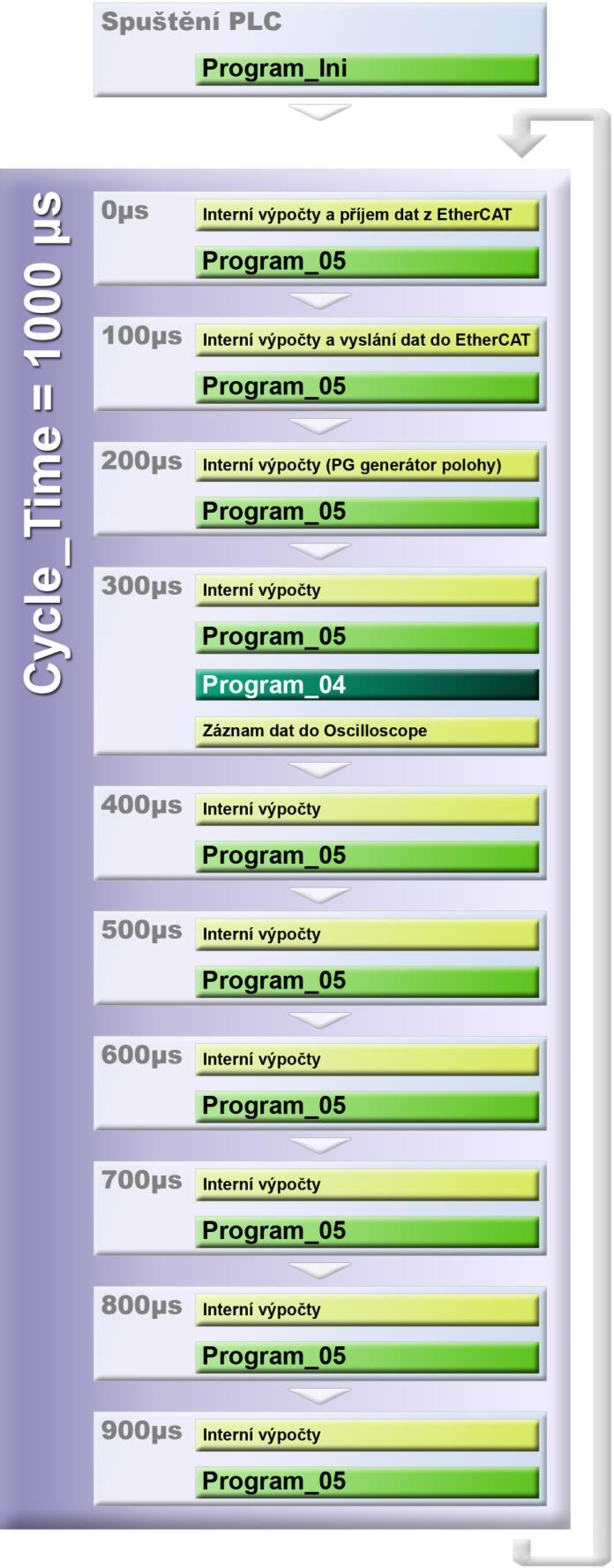
After starting the PLC and successful execution of the Program_Ini function, a cyclic loop call lasting 1000 μs is started.
It is evenly divided into 10 equal time periods called regularly every 100 μs.
-
Time 0 μs The necessary internal calculations are performed and the EtherCAT data is received. Then the function Program_05 is called and the whole function is executed without interruption.
-
Time 100 μs The necessary internal calculations are performed and the data is sent to EtherCAT. Then the function Program_05 is called and the whole function is executed without interruption.
-
Time 200 μs The necessary internal calculations are performed and the data is sent to EtherCAT. Then the function Program_05 is called and the whole function is executed without interruption.
-
Time 300 μs The necessary internal calculations are performed and the function Program_05 is called, which is executed without interruption. Then the function Program_04 is called, which is also executed without interruption. Finally, all the data needed for the Oscilloscope is recorded.
-
Time 400 μs, 500 μs, 600 μs, 700 μs, 800 μs, 900 μs In all of these time periods, the necessary internal calculations are performed and the Program_05 function is called, which is executed in its entirety without interruption. If the computing capacity is free during any cycle, the Program_01, Program_02 and Program_03 functions are operated if necessary.
Tools for PLC debugging
Control Observer
The main tool for debugging the Virtual PLC from the Windows environment is the Control Observer. It is supplied with TG Motion.
It is a set of utilities developed for TG Motion system diagnostics, PLC debugging and Windows applications.
Control Observer contains tools for direct testing and control of servo drives, loading and running PLC code and displaying system timer parameters.
Another group of utilities is used to view, monitor, or modify selected shared memory registers.
Control Observer is a self-executable program Control_Observer_II.exe without installation, which comes with 3 libraries:
TGM_Comm_Int_2.dll- provides communication with TG Motion running on the same computer.TGM_Mini.dll- handles TG Motion running in TGMmini.TGM_Remote.dll- allows connection via LAN to TG Motion running on another computer
Warning
To access the TGM_Data shared memory data, the Select Registers utility uses the Free Registers page, memory type DAT.
Components of Control Observer
- Servo Tester - utility for testing and controlling servo drives.
- PLC Loader - used to load the PLC and start it.
- System Timer - displays the current CPU load of each TG Motion process.
- Oscilloscope - used to graphically display the values of selected registers depending on time.
- Graphic Viewer - used to graphically display a continuous series of selected registers.
Warning
See the Control Observer chapter for a more detailed description.
Console
Diagnostic functions from the PLC_DATA structure are used to write to the RTX Server console.
These are 3 types of diagnostic functions:
- dump the string to the console
- dump the value of the lVal variable (value of the long type) into the console
- output of formatted text to the console
Oscilloscope
Oscilloscope is a separate utility running in TG Motion.
It is used to capture the values of the required registers in the exact time interval Cycle_Time and store them in the shared memory TGM_Oscilloscope.
This happens immediately after the Program_04 function is executed.
The Oscilloscope utility in the Control Observer takes care of displaying the captured data and setting the parameters affecting the recording of values.
Warning
See the Oscilloscope chapter for a more detailed description.
Windows applications
Applications running under the Windows operating system also have access to shared memory. They can be used to read the values of registers or even change them.
Warning
TG Motion runs in a real-time environment, i.e. with a higher priority than processes running under Windows. Therefore, it is not possible to ensure lossless capture of all necessary values from Windows applications, or to provide an operational response to situations that arise.