Electrical installation of the device
Overview
During the electrical installation of the servo amplifier, the safety instructions must be observed and the following principles must be observed:
- The servo amplifier may only be installed by qualified personnel for the installation of electrical equipment.
- Improper mains voltage, incorrect motor or incorrect connection can damage the servo amplifier. Check that the servo amplifier is suitable for the motor. Compare the rated voltage and current of the connected devices. Connect the device according to the relevant wiring diagrams (chapter "Description of connectors").
- Make sure that the maximum permissible rated voltage at the terminals is not exceeded by more than 10% even in the most unfavorable situations (see ČSN EN 60204-1).
- Excessive current rating of the external fuse will endanger cables and equipment. The supply voltage fuse and the 24 VDC control circuit supply must be installed by the user.
- The status of the servo amplifier must be monitored to identify critical situations.
- Configuration software can be used to change the servo amplifier settings. Any changes or interventions not previously consulted and approved by the equipment manufacturer will void the warranty.
Install the servo amplifier electrical system as follows:
- Select cables in accordance with the ČSN EN 60204 standard.
- Install a servo amplifier shield and ground that meets EMC requirements. Ground the mounting plate and motor cover.
- Connect the servo amplifier and connectors according to common principles and recommendations for suppressing electromagnetic interference.
Shield connection procedure
DC BUS connection procedure with shield connection:
- Use the shortest cables possible according to the distance and arrangement of the individual devices in the cabinet.
- Remove 25 to 35 mm of outer insulation from both ends of the cable, including the shielding, and terminate with shrinkable tube so that the cut strands cannot make unwanted contact with live parts of the wiring.
- Strip the ends of all conductors and fit the contact ferrules.
- Remove the outer insulation in a width corresponding to the cable clip (usually 15 - 20 mm) approximately in the middle of the cable. Be careful not to damage the cable braid.
- Connect the ferrule assembled wires to the connector housings and plug them into the TGZ device.
- Place the shielding clip on the stripped part of the cable and fix it, including the cable, to the base plate using screw into the prepared threaded hole.
- The cable shielding must make surface contact with base plate after tightening the screw.
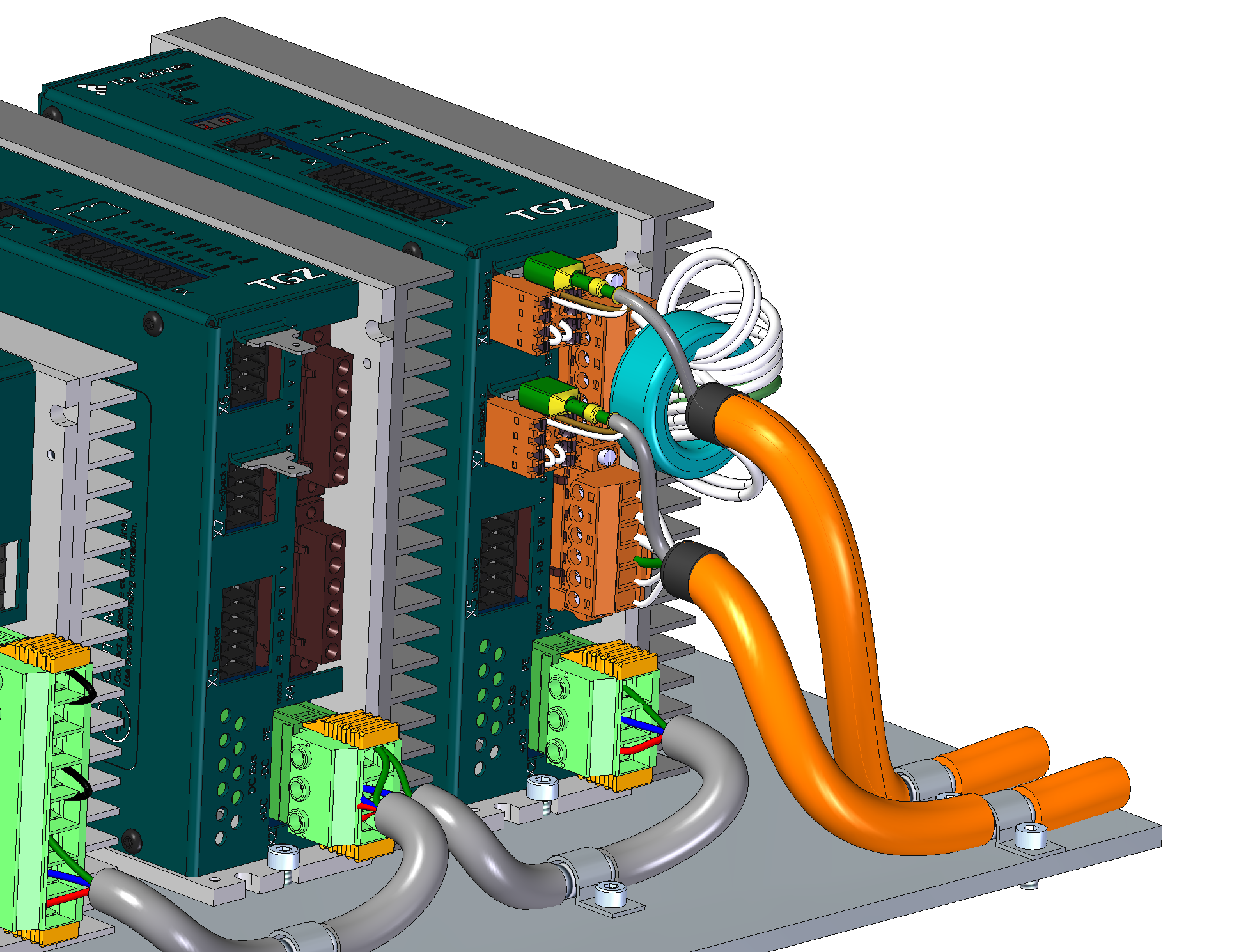
Motor cable connection procedure with shield connection:
- Use only original TG Drives cables - the shortest possible cables according to the mutual distance and arrangement of individual devices in the switchboard.
- Remove a suitable length of outer insulation from the motor cable to allow the connectors to be conveniently connected to the servo amplifier without mechanical stress.
- Shorten the outer braid of the motor cable and insert it into the heat shrink tube.
- Do not shorten the shielding of the feedback pair. Install a 6.3 mm faston at the end of this shielding. You can put the feedback wires into heat shrink tube optionally.
- Remove a strip of outer insulation approximately 15-20 mm wide approximately 15-20 cm from the end of the wires. Take care not to damage the cable braid.
- Fit ferrules adequate to the cross section of the wires onto the prepared stripped ends.
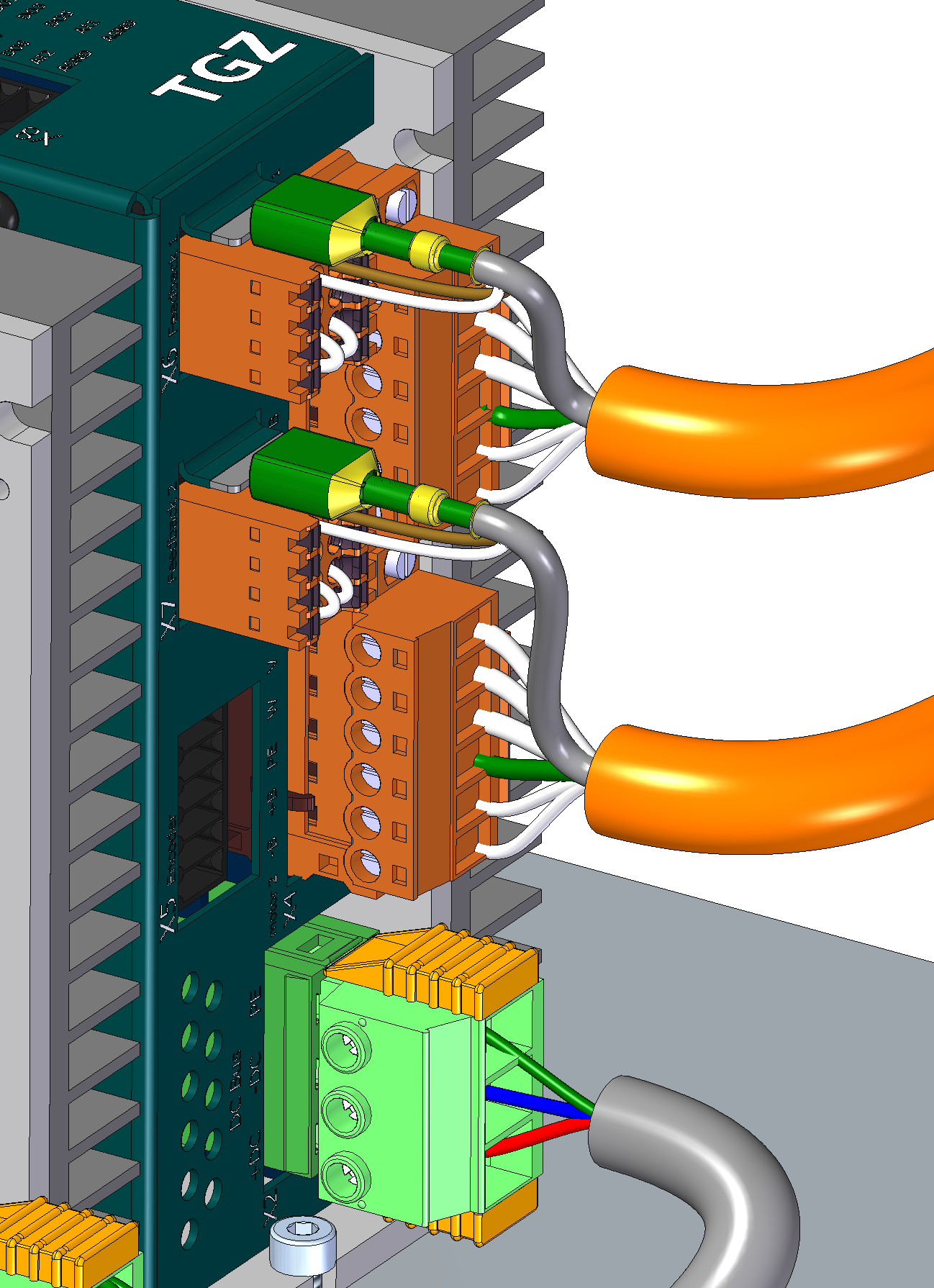
- Connect the wires to the housings according to the wiring diagram and connect it to the TGZ device.
- Attach the motor cables to the mounting plate using sheet metal clips at the location of the previously removed strip of outer insulation.
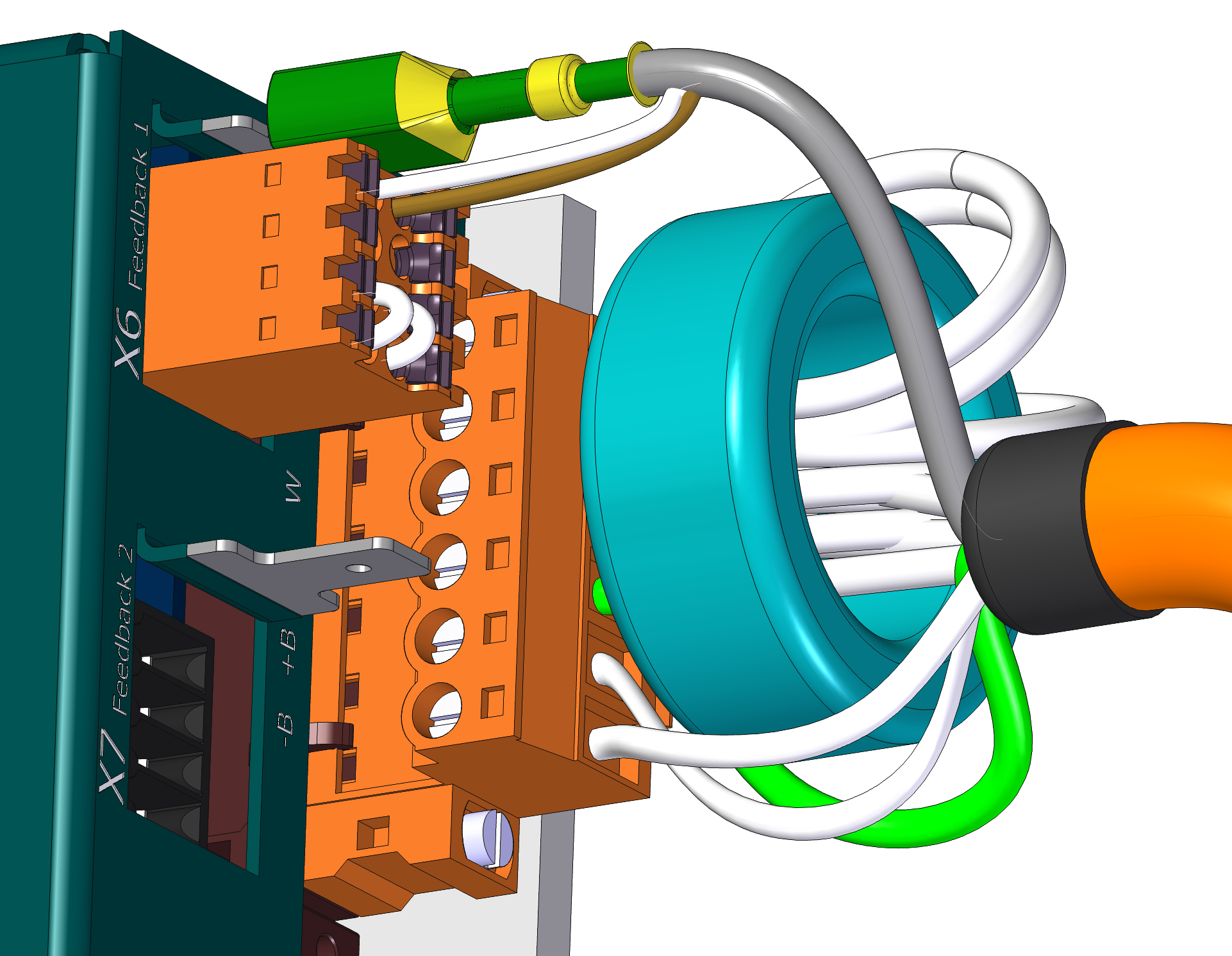
- Connect the faston on the feedback shielding to the prepared counterpart connector on the servo amplifier cover. The counter piece is located next to the feedback connector.
- If you are using motor cables longer than 5 m it is strongly recommended to use a ferrite toroid on the phase conductors. It is ideal to make one turn around the core as shown in the picture.
- In the case of cables longer than 20 m, the use of a ferrite toroid is insufficient from an EMC point of view. Additionally the ring could overheat. In this case it is necessary to replace the ferrite toroid with a motor choke. Contact TG Drives sales for further information about additional motor choke.
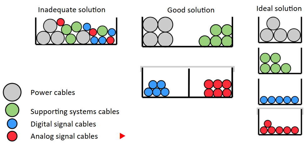
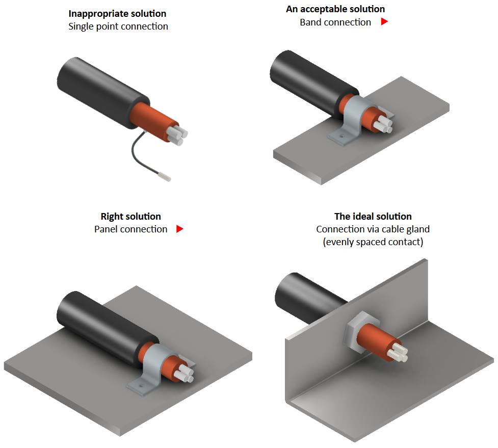
Shielding technology
The figures show an unsuitable and suitable shield connection:
Reducing EMI
The following guidelines will help you reduce electrical interference problems in your application:
- Ensure a good connection between the parts in the cabinet. Connect the rear panel and the cabinet door to the cabinet body using stranded wires. Never rely on hinges or mounting screws to provide grounding. Ensure that the entire rear surface of the servo amplifier panel is electrically connected. It is recommended to use electrically conductive panels, for example made of aluminum alloys or galvanized steel. For metal panels with a coating or other finish, remove the non-conductive layer behind the servo amplifier.
- Ensure a good ground connection. Connect the switchboard to a good ground. The earth conductors should have the same cross-section as the supply conductors, or one degree smaller.
- Use the cables provided by the manufacturer. If a cable is used which also contains the brake control wires, the brake control wires must have a separate shield.
- Ground the shield at both ends. Ground all shields with as large an area as possible (to achieve low impedance). Connect them to the metal cover of the connectors or shield terminals wherever possible. For cables entering the switchboard, connect the shield around the entire cable circumference (360 °). Never connect just one "wire".
- The cables should not be extended, as this could disturb the shielding and thus the signal processing. To achieve the maximum cable length, use cables with the appropriate cross-section according to ČSN EN 60204 and made of the recommended material.
- Connect the cables correctly. If split cables need to be used, use connectors with a metal cover to connect them. Ensure that both covers are connected to the shield around the entire circumference of the cable (360 °). No part of the cable should remain unshielded. Never connect a split cable using a terminal block.
- The wires between the individual servo amplifiers must also be shielded.
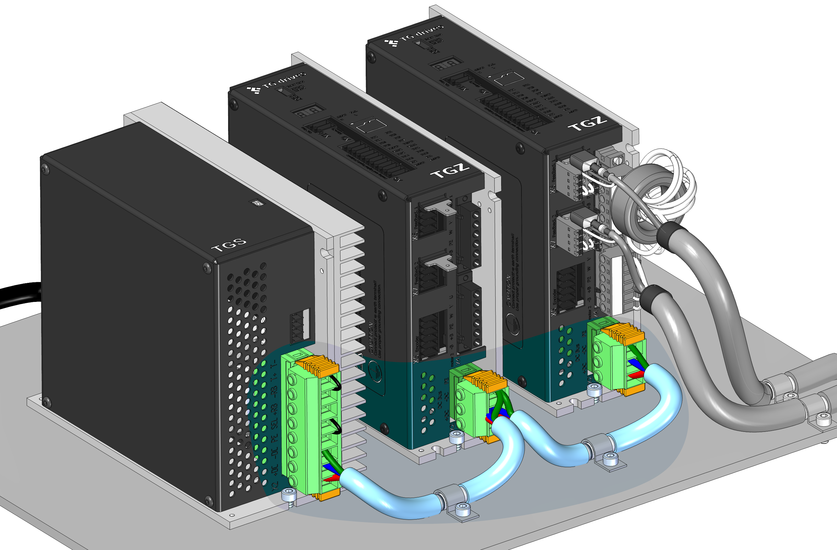
Recommended cabling
The figures below show the recommended cabling: