Interpolator
The CNC is a software module that executes a sequence of motion (G-instruction) and input/output commands (M-function) given by the G-code. It includes the Interpolator module.
Interpolator
The interpolator module calculates the positions and speeds of the individual servo drives (axes) so that the resulting motion is uniformly performed by all axes.
There is linear interpolation (motion along a straight line), circular interpolation (motion along a circle performed by two arbitrary axes), or helical interpolation (two axes perform motion along a circle, the others perform linear motion).
To calculate three independent final trajectories for multi-axis motion, TG Motion offers three independent interpolators, each of which can operate up to ten actuators.
The shared memory TGM_Interpolator serves as an interface between the CNC module and other applications (PLC, Win applications).
Most registers are read-only and display the current CNC module values.
Since the G-code is usually written in units of [mm], the Interpolators also work with units of [mm].
To set the conversion [mm] to [inc], use the Command structure or the Ratio register (see below).
PLC and Windows application competence
PLC
It sets the basic parameters of the Interpolator, operates M-functions and solves the emergency stop of the Interpolator. The Interpolator cannot be started from the PLC.
Windows applications
They convert the G-code into binary intercode, fill the Interpolator buffer in shared memory with it, and start and stop the Interpolator. The Interpolator buffer is not accessible from PLC or Windows applications.
G-code
G-code is the name of the programming language that controls NC and CNC machine tools. This is a code in text format that tells the machine tool what action to perform. In G-code, the most commonly used commands include Ginstruct and M-function. They are always prefixed with a letter (G, M) and a numeric parameter that specifies what the instruction should do. The individual G-instructions are precisely defined, most of the M-functions can be defined by the user.
Example of part of the G-code
G00 X60.6051 Y40.7723
G42
M51
G02 X0 Y-2.5202 I3.0336 J-1.2601
G02 X0.922 Y-1.5646 I6.0604 J2.5173
G02 X1.079 Y-1.0269 I4.2143 J3.3479
G02 X2.2624 Y-1.3678 I9.8772 J13.7817
G02 X1.9856 Y-0.8109 I6.1778 J12.2908
G02 X3.015 Y-0.7892 I8.8515 J27.6632
G02 X6.2889 Y0 I3.1444 J33.011
M50
G40
G00 X-28.9085 Y30.4365
G42
M51
G40
M2
G-instructions
They are mostly used for fast positioning, sliding movement along a straight line or arc, drilling or cutting. The Interpolator takes care of their execution. The execution of G-instructions can be interrupted by M-functions. In this case, the Interpolator can wait for the M-function to execute and then continue executing the G-code.
Table of G-instructions
| Marking | Description |
|---|---|
| Basic G-instructions | |
| G0 | Quickdraw |
| G1 | Linear interpolation |
| G2 | Circular interpolation CW |
| G3 | Circular interpolation CCW |
| G4 | Delay [sec] |
| G25 | Calling a subroutine |
| G26 | Cycle call |
| G27 | Program jump |
| G29 | Instructions or text note |
| G40 | Cancel correction |
| G41 | Correction to the left of the contour |
| G42 | Correction to the right of the contour |
| G53 | Zero point offset cancellation |
| G54 | Zero point displacement |
| Extended G-instructions | |
| G90 | Absolute Programming |
| G91 | Incremental programming |
| G92 | Setting coordinate values |
M-functions
If any M-function is part of the code, its handling must be ensured in the user PLC code. The interpolator does not deal with M-functions, it just waits for some of them to be processed. M-functions can be user-defined with exceptions (see the M_Function_Parameter register).
Movement and continuous M-functions
Motion M-functions (Mx, where x < 1000) - the execution of the G-code is stopped, the PLC services the M-function and after its completion sets the register M_Func = 0.
The interpolator then continues to execute the G-code with the next instruction.
Continuous M-functions (Mx, where x > 1000) - the PLC starts servicing the M-function, but the Interpolator does not wait for the M-function to be serviced and continues executing the G-code.
Table of supported M-functions
| Marking | Description |
|---|---|
| M0 | Program stop |
| M2 | G-code termination, can be redefined |
| M3 | CW spindle rotation, can be redefined |
| M4 | CCW spindle rotation, can be redefined |
| M5 | Spindle stop, can be redefined |
| M6 | Tool change, can be redefined |
| M7 | Cooling on, can be redefined |
| M8 | Enable erasing, can be redefined |
| M9 | Cooling and lubrication shutdown, can be redefined |
| M17 | Return from subroutine (RETURN), can be redefined |
| M29 | Text message output (PRINT), can be redefined |
| M30 | G-code termination, can be redefined |
| M80 | Mirroring off |
| M81 | X-axis mirroring |
| M82 | Mirroring in the y-axis |
| M83 | Mirroring in z-axis |
| M84 | Mirroring in x and y axes |
| M85 | Mirroring in x and z axes |
| M86 | Mirroring in y and z axes |
| M87 | Mirroring in x, y and z axes |
| M99 | Define default feed value, can be redefined |
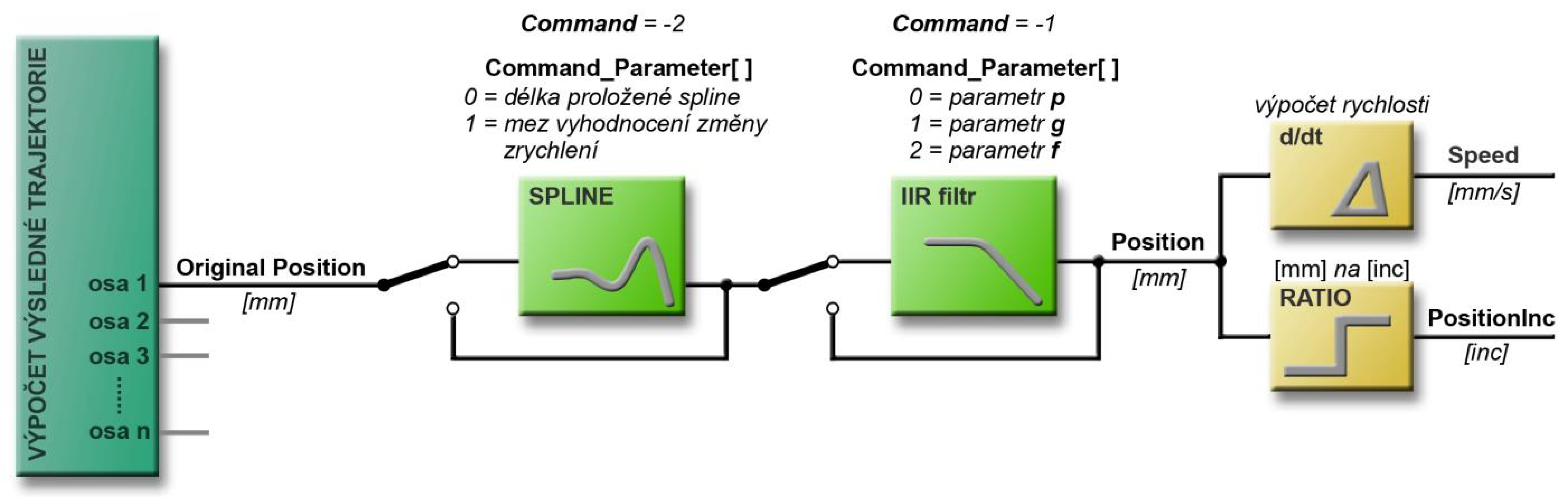
Trajectory smoothing
G-code often works with polynomials composed of short segments, and sometimes instantaneous speed changes can occur due to incorrectly written code. Any instantaneous changes in speed can result in undesirable acceleration in some of the axes and thus mechanical shock in some of the actuators. Two tools are used to smooth the calculated trajectory.
Spline
Spline - smoothing function
The Spline function should be used in the case of incorrectly created G-codes, in which individual sections on the do not follow each other smoothly or continuously, or in the case of G-codes in which the resulting trajectory is created by of linear segments with coarse division. Spline is also useful for smoothing out the step change in velocity that results from from a mathematical model of mechanics (e.g. tilting heads).
The Spline function is activated in all axes at the same time, it cannot be applied to only some axes. When activated the change in acceleration (jerk) is controlled in each axis. If a change greater than the allowed change is found, it will interleave the with a spline curve at that location.
Warning
The longer the spline length (the size of the spline buffer), the better the smoothing. Smoothing with Spline is at the expense of positioning accuracy.
Activation and parameterization of Spline
The Spline function is activated and parameterized by the Command structure of the Interpolator.
For the register value Command = -2 the Command parameters have the following meaning:
Command_Parameter[0] - specifies the number of points through which the spline is interleaved. This determines the size of the spline buffer.
The parameter setting range is 50-500 points/steps.
With Cycle_Time = 500 μs the calculation step is 100 μs, with Cycle_Time = 250 μs the calculation step is 50 μs.
Disabling the spline function is possible by setting the spline length to zero (Command_Parameter[0] = 0).
Command_Parameter[1] - defines the limit of the acceleration change evaluation (jerk), i.e. from which acceleration the Spline function is activated.
It is expressed in units of [mm/s³].
The appropriate setting value is 1 000 000 mm/s³.
After setting both parameters, the Command register must be set to -2. After the TG Motion command is executed, this register is reset.
Movement delay
The movement after passing the Spline function is delayed by the length of the Spline buffer compared to the positioning calculated by the interpolator. All axes are always positioned synchronously because the buffer size is the same for all axes. Even M-functions are called synchronously with the resulting motion, because the same buffer size is used for them.
Example of Spline setup
Example of enabling the Spline function with a spline length of 20 ms (with Cycle_Time = 500 μs).
The Command_Parameter values must be set first and the last register value Command = -2.
Interpolator.Command_Parameter[0] = 200;
Interpolator.Command_Parameter[1] = 1000000;
Interpolator.Command = -2;
IIR Filter
IIR Filter - smoothing function
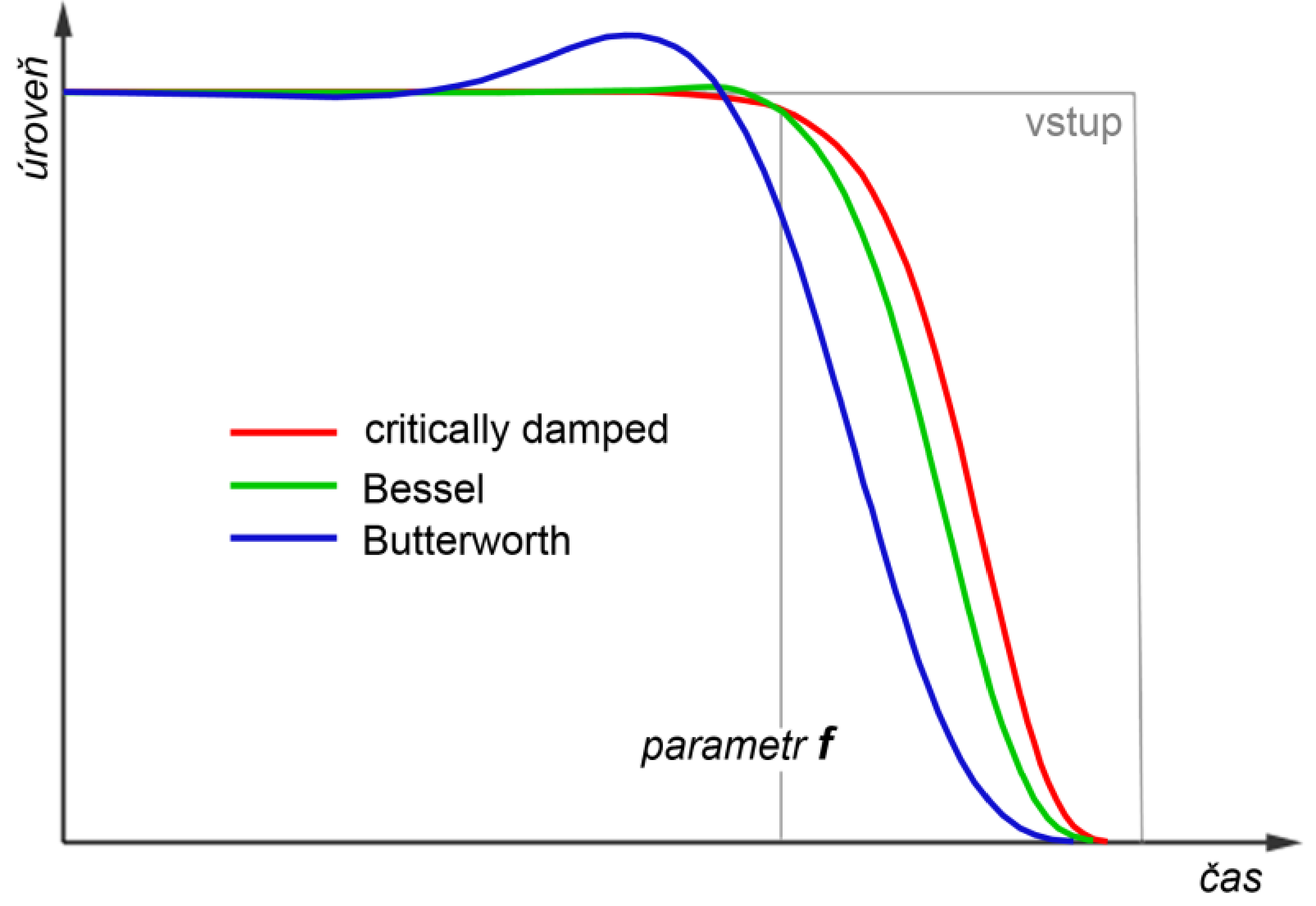
The IIR Filter (Infinite Impulse Response) can be used to smooth the resulting motion speed and remove unwanted rapid changes. It is a mathematical model of a linear low-pass filter with a steepness of 12 dB per octave (2-Pole) calculated according to the relation:
with the possibility of setting three parameters:
- p, q - parameters setting the filter waveform (see table)
- f (cutoff) - time for the filtered trajectory to return to the original calculated trajectory
Parameter values for some filter types
| p | q | filter type | description |
|---|---|---|---|
| √2 | 2 | Butterworth | there is a stroke before f, small delay |
| 3 | 3 | Bessel | slight stroke, smooth progression, more delay |
| 2 | 1 | critically damped | smooth gradual progression without stroke, largest delay |
Activation and parameterization of IIR Filter
The IIR Filter parameter values can be set using the Command structure.
For the register value Command = -1 the Command parameters have the following meaning:
Command_Parameter[0]- sets the parameter p of the filter.Command_Parameter[1]- sets the q parameter of the filter.Command_Parameter[2]- specifies f - time of return to the original trajectory.
Warning
Parameter values are of type Integer, the actual physical value of the parameter is obtained by dividing the parameter value by \(1 \cdot 10^6\) (Command_Parameter[1] = 1000000, filter parameter = 1,0).
Command_Parameter[3]- sets the filter activity bit mask for each axis. Only the first 10 bits are used for the 10 axes, the other bits are ignored (see registers).
Movement delay
IIR Filters delay the calculated movement. The delay depends on the input data, it varies dynamically and its size cannot be determined in advance. The M-functions are signaled from the running G-code when the Interpolator is "stationary", but the physical movement of the actuators does not have to be completed yet.
Warning
When using the IIR Filter, the actuator will "float" behind the Interpolator and it is always necessary to wait until the physical movement of all actuators is actually complete.
The setting of IIR Filter parameters is common for all Interpolator axes.
The filter can be activated independently for each axis according to the Command_Parameter[3] register bit mask.
It is therefore necessary to take into account that the resulting movement of the axes after the filter application may not be synchronous with each other as originally calculated.
Command Structure
Registry Command_Parameter
This chapter describes the meaning of the Command_Parameter[ ] registers for selected values of the Command register.
Setting gear ratio mm to inc - Command = 1024
The G-code usually works implicitly with the unit [mm], so the Interpolator also works in units of [mm].
Since servo drives work with increments [inc], it is necessary to determine the gear ratio inc/mm according to the number of inc/turn of the servo drive (Servo[x].Resolution).
It is set using the Command structure of the corresponding Interpolator.
The calculated position in the given axis is then multiplied by the transmission ratio and the calculated position is then sent to the actuator.
| Command_Parameter | description |
|---|---|
| 0 | specifies the axis number for which the ratio is set [0-9] |
| 1 | gear ratio counter [inc] |
| 2 | gear ratio denominator [mm] |
Setting the current position - Command = 2048 and Command = 2049
Use Command = 2048 and Command = 2049 to set the current position of the interpolator. After executing the 2048 command, the system reports the position on the trajectory, in the second case the position off the trajectory. For both variants, all Command_Parameter[0-9] take on the same meaning.
| Command_Parameter | description |
|---|---|
| 0 | current position in axis 0 [inc] |
| ... | ... |
| 9 | current position in axis 9 [inc] |
Setting IIR Filter parameters - Command = -1
| Command_Parameter | description |
|---|---|
| 0 | Filter parameter p - setting the filter waveform (in combination with parameter q) |
| 1 | Filter parameter q - setting the filter waveform (in combination with parameter p) |
| 2 | filter parameter f - time for the filtered trajectory to return to the original trajectory |
| 3 | IIR Filters activity bitmask for each axis of the Interpolator. Example: xxxx xx00 0000 0101 - only IIR Filter for axis 0 and axis 2 is active |
Setting Spline parameters - Command = -2
| Command_Parameter | description |
|---|---|
| 0 | Specifies the number of points that the spline is interleaved with; the setting range is 50-500 points |
| 1 | upper limit of acceleration change evaluation [mm/s³] |
LookAheadBuffer structure
Description of the structure
The LookAheadBuffer structure is a table of important parameters of eight sections - G-code items following to each other. The first item in the table is always the section currently being performed, the next items are the seven immediately the following sections.
LookAheadBuffer acts as a shift buffer. When the current section is executed, the table data is shifted, the first one is again the currently executing section and the 8th following section from the currently executing section is inserted in the last place. The LookAheadBuffer structure is filled by the Interpolator. From the PLC point of view, its registers are read-only.
The G-code section
A segment is a single G-code item, either a G-instruction (G0-G3) or a motion M-function that has meaning in terms of motion (M3-M999).
Using the structure
The LookAheadBuffer structure is used to customize the technology according to the instructions and functions of the following sections, or according to their values. Since the Interpolator cannot be started or stopped from the PLC (except for emergency stops), it is it is necessary to handle everything necessary during the operation of existing M-functions. This must be ensured by the PLC code author. During the M-function, the PLC can, for example, change the angle of the machining head in the corner of the square according to the tangent of the following function; it can use the Rel_Speed register to slow down the motion if it knows that a large tangent change will follow. When moving in a circle, a tangent is available at all times and can be used to turn the head. When short segments can also be smoothed by gradually turning the head to smooth the broken line. To perform all these operations it is necessary to know what will follow the section you are currently performing. For this purpose, the structure can be used LookAheadBuffer.
Warning
Sometimes a negative M-function number may appear in the Movement_Code register for Movement_Type = 2.
This is an internal function of TG Motion that does not need to be manipulated.
The individual registers of the LookAheadBuffer structure are described in the Appendix chapter.
Apendix
Overview and description of registers of the Interpolator structure
| name | access | offset | description |
| Number | R | 0 | interpolator number, can take values 0, 1, 2 |
| Number_Axes | RW | 4 | number of axes the interpolator works with; the allowed range is 1-10 |
| Buffer_Size | R | 8 | maximum number of G-code sections, values allowed are 1000-100000 |
| Command | RW | 12 | command: 4 = emergency stop on trajectory 5 = emergency stop (after stop reports off trajectory)8 = normal stop on trajectory 9 = normal stop (off trajectory) 1024 = setting of gear ratios (mm per inc) - see chap. Command 2048 = current position setting (on trajectory) - see chap. Command 2049 = set current position (off-trajectory) - see chap. Command -1 = setting IIR Filter parameters - see chap. Command -2 = Spline parameter settings - see chap. Command |
| Command_Parameter [0-11] (12 registers) |
RW | 16 | 12 integer type parameters whose meaning and values depend on the Command function type |
| Command_Status | R | 64 | current status of the executed command: 0 = the previous command was successfully executed and the next command can be activated 1 = the current command is executing -1 = an error occurred during the execution of the command |
| Status | R | 68 | current interpolator status: 1 = trajectory movement in progress 3 = stop at end of trajectory 4 = at least one trajectory segment in buffer, start can be called 6 = stopping after crash ramp 7 = interpolator stopped after crash stop 8 = interpolator was stopped during buffer filling |
| Act_Part | R | 72 | number of the currently executing section |
| Address_External_Position | RW | 76 | offset of the TGM_Data address where the position of the external sensor is stored; the value is of type integer |
| M_Func | RW | 80 | M-function value; for M < 1000 the Interpolator stops and waits for this value to be reset; then continues with the next section; for M > 1000 it continues executing the G-code |
| Act_G_Func | R | 84 | value of the currently executing G-instruction |
| Act_M_Func | R | 88 | value of the currently executing M-function |
| Last_Cont_M_Func | R | 92 | stored value of the last continuous M-function (M > 1000) |
| Run_Flag | R | 96 | - the lower 16 bits show the status of the current section: 0 = STOP (interpolator is inactive) 1 = RUN (motion G-instruction is executed) 2 = WAIT_WINDOW (for rotary machining) 3 = WAIT_PULSE (for rotary machining) 4 = WAIT_MFUNC (M-function execution has started) 5 = WAIT_MFUNC_WAIT_FOR_END (waiting for M-function to finish) - the upper 16 bits are the status of the speed progress: 1 = no motion 2 = accelerating 3 = desired motion speed reached 4 = decelerating 5 = next speed section 6 = decelerating on last section 7 = decelerating after emergency ramp notefrom TGM420 version |
| Tool_Number | R | 100 | number of the current tool (drilling, milling, ...) note: from version TGM420 |
| Orig_Position (10 registers) | R | 376 | calculated coordinates of all axes [mm] |
| Position (10 registers) | R | 456 | Spline or IIR Filter adjusted coordinates [mm] |
| PositionInc (10 registers) | R | 536 | Position coordinates multiplied by Ratio [inc] |
| Backlash (10 registers) | R | 616 | current clearance value for each axis [inc] |
| Offset (10 registers) | RW | 696 | offset values are added to PositionInc, these values are set by the user [inc] |
| Speed (10 registers) | R | 776 | current speed of each axis after Spline and IIR [mm/s] |
| Ratio (10 registers) | RW | 856 | conversion ratio (multiplier) of G-code units (usually mm) to increments (actuator positions) |
| M_Function_Parameter (32 registers) |
R | 936 | parameters of the M function from the G-code, a total of 26 values by letters in the alphabet; some letters cannot be used because they are reserved by the system reserved parameters (indices are counted from 0): G = index 6 M = index 12 N = index 13 P = index 15 |
| Rel_Speed | RW | 1192 | relative rate of interpolated motion, coefficient in the range 0.01-2 (1-200%) |
| Set_Speed | R | 1200 | required speed from G-code (given by G-code F-instruction or speed table) [mm/min] |
| Act_Speed | R | 1208 | current speed [mm/min] |
| Move_Distance | R | 1216 | current total distance travelled [mm] |
| LookAheadBuffer | R | 2048 | table of information about the sections that will follow; a total of 8 structure items described in the following table; the first item describes the section currently being executed; the size of each item is 1792 bytes note: from TGM420 version |
Overview and description of registers of the LookAheadBuffer structure
| name | access | offset | description |
| AllParams (26 registers) |
R | 0 | all specified M-function addresses from a particular G-code for a given section (26 letters of English abecedent) |
| Tangent | R | 208 | current tangent of motion in the XY plane; if the currently executed segment is an arc (G2 or G3), the tangent changes continuously; for future segments it determines the initial tangent of motion |
| MovementType | R | 216 | record type: 0 = invalid record (number of remaining legs to execute is less than the current index of the LookAheadBuffer table), less than 8 legs remain before the end of motion execution 1 = motion function (G0, G1, G2, G3) 2 = M function |
| MovementCode | R | 220 | G-instruction or motion M-function number (the number of the continuous M-function does not appear in this register but appears in AllParams in the letter M) |
| Plane | R | 224 | - plane of circular interpolation: 17 = XY 18 = XZ 19 = YZ - other planes not defined |
| Tool | R | 228 | tool number |
| EndPos (10 registers) | R | 232 | end position of each axis section [mm] (absolute coordinates) |
| StartAngle | R | 312 | initial arc angle [°] - the angle of the arc center's junction with the initial point; the register value is cyclic (0-360); for linear motion or M-functions, the register value is greater than 1038 |
| EndAngle | R | 320 | arc end angle [°] - angle of the arc center's junction with the end point; the register value is cyclic (0-360); for linear motion or M-function it is greater than 1038 |
| Radius | R | 328 | - radius of arc [mm] - for linear motion or M-functions the register is zero |