Cable connections
Z1 - Motor cable and Hiperface DSL (304)

Z2 - Motor cable and Hiperface DSL (283)

Z3 - Motor cable and Hiperface DSL CSTA 8p (305)

Z4 - Motor cable and Hiperface DSL (306)

Z5 - Motor cable TGZ (226)

Z6 - Motor cable TGZ (Z6)

Z7 - Motor cable TGZ CSTA 8p (84)

Z8 - Motor cable TGZ (21)

Z9 - Cable ENDAT 2.2 (293)

Z10 - Cable ENDAT 2.2 ITEC (343)

Z11 - Cable ENDAT 2.2 (319)

Z12 - Connection Renishaw (Tonic) - TGZ

Z13 - Thermistor connection - TGZ

Z14 - Cable SSI/BISS 5V

Z15 - Cable SSI/BISS 12V

Z16 - Cable - free leads SSI/BISS 5V (395)

Z17 - Motor cable TGZ Boost

Z18 - External IRC cable

Z19 - Motor cable TGZ-S-48-50/100-UNI

Z20 - Feedback cable TGZ-S-48-50/100-UNI

Z21 - TGZ-S-48-50/100 RI connection with iTEC

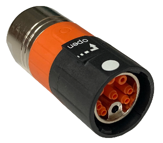
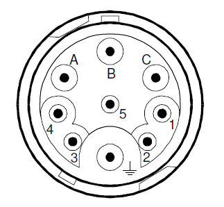
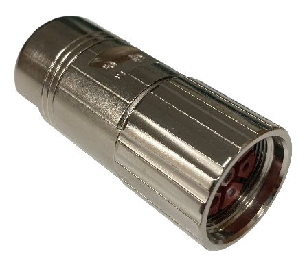
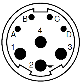
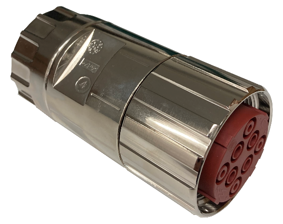
INTERCONTEC 09P_Y
-
Cable type connector view
-
Motor type connector view
Z22 - TGZ-S-48-50/100 RI connection with straight connector / S1 / S2 / S3 / S4 (08p)

INTERCONTEC BSTA 08p
-
Cable type connector view
-
Motor type connector view
Z23 - TGZ-S-48-50/100 RI connection with straight connector 1.5 / S4 vel. 1.5 (CSTA 8p)

INTERCONTEC CSTA 8p
-
Cable type connector view
-
Motor type connector view
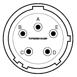
Z24 - TGZ-S-48-50/100 RI connection with Amp TVP00RW-15-05P acc. MIL-DTL-38999 III

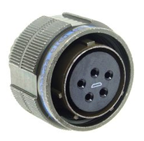
Amphenol TVP00RW-15-05P
-
Cable type connector view
-
Motor type connector view
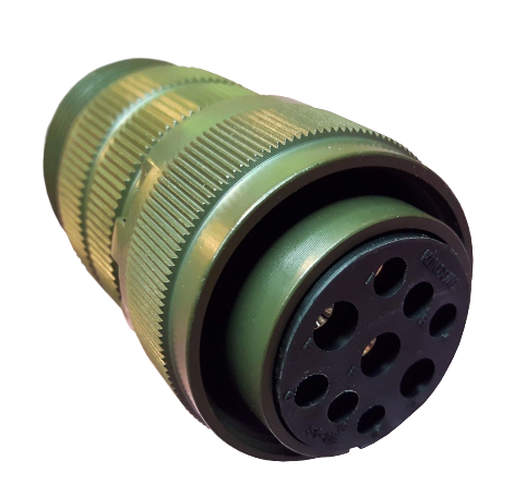
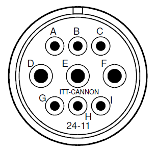
Z25 - TGZ-S-48-50/100 RI connection with ITT-Cannon 24-11

ITT-Cannon 24-11
-
Cable type connector view
-
Motor type connector view
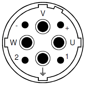
Z26 - TGZ-S-48-50/100 RI with BISS
Wiring diagrams for other types of sensors used are available on request directly from the device manufacturer. Below you can find the wiring diagram for the BISS interface. The first line of the connector name on the servo amplifier side is assigned to the TGZ-S-48-100/250 and TGZ-S-48-100/300. The second line of the connector name is assigned to the TGZ-S-48-50/100.

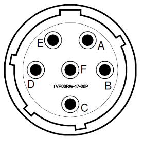
TVP00RW-17-06P
-
Cable type connector view
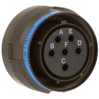
-
Motor type connector view
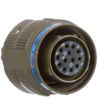
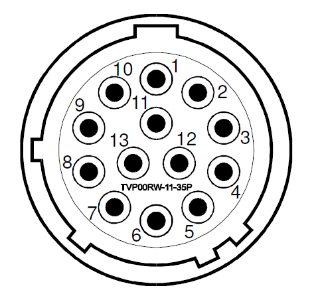
TVP00RW-11-35P
-
Cable type connector view
-
Motor type connector view
Z27 - TGZ-S-48-100/xxx RI connection with iTEC

INTERCONTEC 09P_Y
-
Cable type connector view
-
Motor type connector view
Z28 - TGZ-S-48-100/xxx RI connection with straight connector / S1 / S2 / S3 / S4 (08p)

INTERCONTEC BSTA 08p
-
Cable type connector view
-
Motor type connector view
Z29 - TGZ-S-48-100/xxx RI connection with straight connector 1.5 / S4 vel. 1.5 (CSTA 8p)

INTERCONTEC CSTA 8p
-
Cable type connector view
-
Motor type connector view
Z30 - TGZ-S-48-100/xxx RI connection with Amp TVP00RW-15-05P according to MIL-DTL-38999 III

Amphenol TVP00RW-15-05P
-
Cable connector
-
Motor type connector view
Z31 - TGZ-S-48-100/xxx RI connection with ITT-Cannon 24-11 connector

ITT-Cannon 24-11
-
Cable connector
-
Motor type connector view
Z32 - TGZ-S-48-100/xxx RI with two-cable BISS
Wiring diagrams for other types of sensors used are available upon request directly from the device manufacturer. Below you will find the wiring diagram for the two-cable interface for BISS. The first row of the connector name on the servo amplifier side is assigned to TGZ-S-48-100/250 and TGZ-S-48-100/300. The second row of the connector name is assigned for TGZ-S-48-50/100.

TVP00RW-17-06P
-
Cable connector
-
Motor type connector view
TVP00RW-11-35P
-
Cable connector
-
Motor type connector view