Connector description
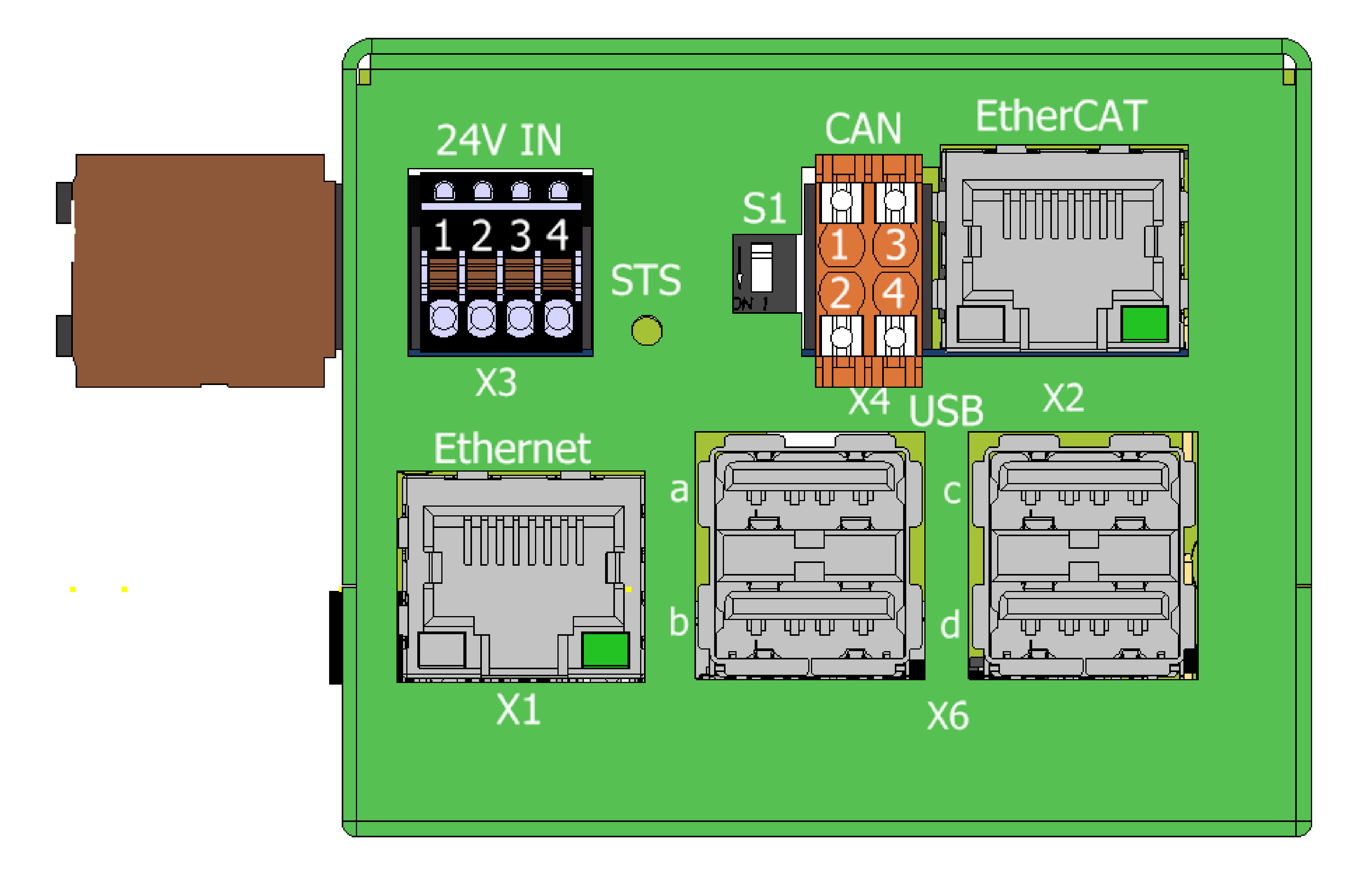
View of the ENET/ECAT side
-
X3 - Input power

-
Weidmüller BLF 2.50/04/180 SN OR BX
pin # Marking Description AWG 1 +PWR 24V 24V PSU input 20-28 2 +PWR 24V 24V PSU input 20-28 3 PWRCOM Common input 20-28 4 PWRCOM Common input 20-28 -
X4 - CAN

-
Weidmüller BCZ 3.81/04/180 SN OR BX
pin # Marking Description AWG 1 CANH CAN signal H 16-25 2 CANL CAN signal L 16-25 3 CANGND CAN isolated ground 16-25 4 NC No connection 16-25
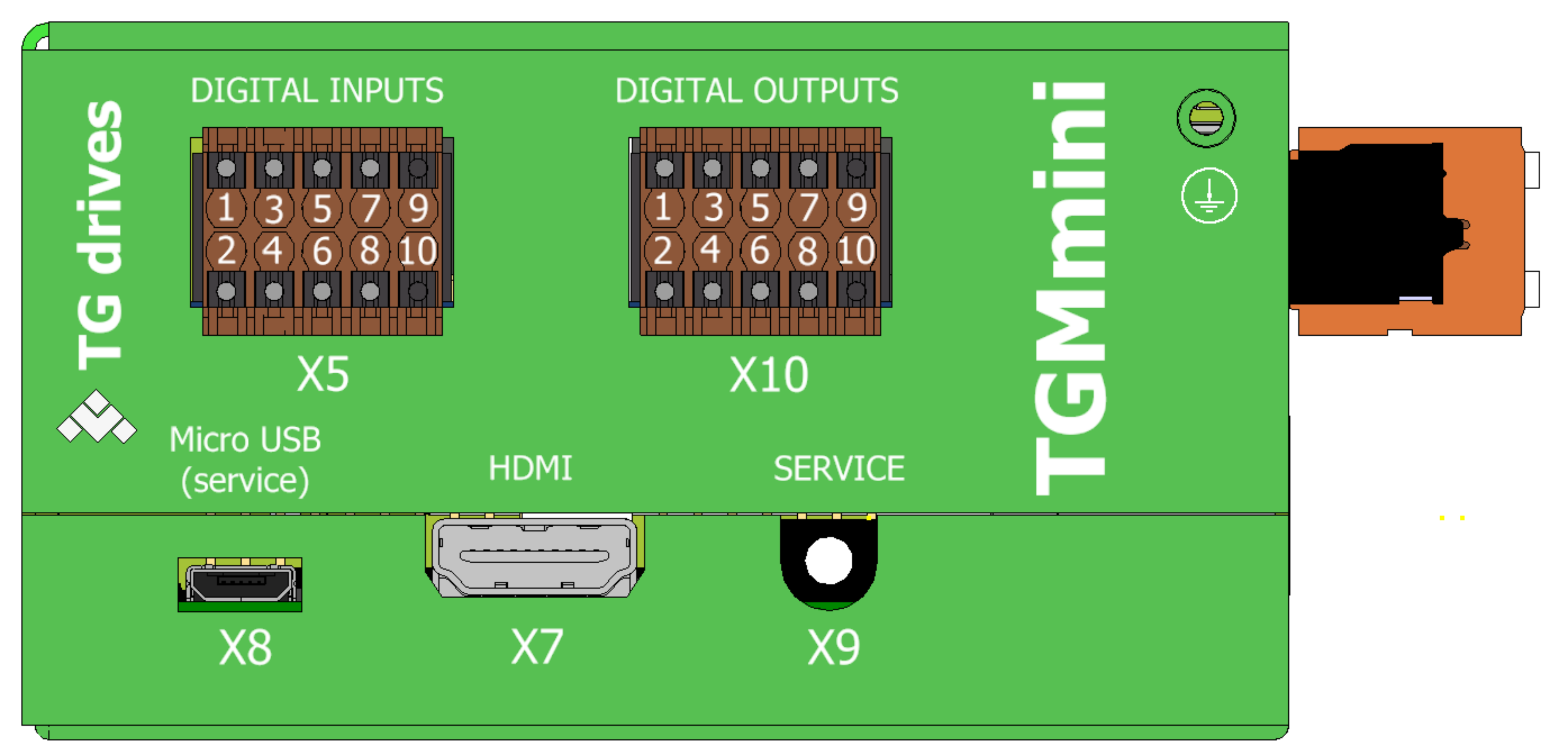
IO/USB/SD side view
-
X5 - Digital inputs

-
Weidmüller B2CF 3.50/10/180 SN OR BX
pin # Marking Description 1 IN1 Digital input no. 1 2 IN2 Digital input no. 2 3 IN3 Digital input no. 3 4 IN4 Digital input no. 4 5 IN5 Digital input no. 5 6 IN6 Digital input no. 6 7 IN7 Digital input no. 7 8 IN8 Digital input no. 8 9 IN9 Digital input no. 9 10 IN10 Digital input no. 10 -
X10 - Digital outputs
-
Weidmüller B2CF 3.50/10/180 SN OR BX
pin # Marking Description 1 OUT1 Digital input no. 1 2 OUT2 Digital input no. 2 3 OUT3 Digital input no. 3 4 OUT4 Digital input no. 4 5 OUT5 Digital input no. 5 6 OUT6 Digital input no. 6 7 OUT7 Digital input no. 7 8 OUT8 Digital input no. 8 9 OUTCOM DO common ground 10 OUTPWR DO common PSU 24V DO supply
The power supply of the digital outputs must be complete, i.e. the OUTCOM and OUTPWR 24 V pins must be properly connected. In the case the ground wire to OUTCOM is broken, on all output pins OUT0 – OUT7 appears voltage of about 21 V. The outputs can subsequently and unexpectedly switch ON the devices connected to these outputs. To alleviate this problem, a safety relay (like OMRON K8AK-AS1) must be used and properly connected.
TGDrives, s.r.o. is not responsible to any damages and/or injuries caused by wrong 24 V power connection. Only properly qualified personnel are permitted to make the device installation and start up.
-
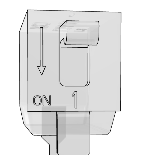
S1 - CAN bus termination
-
DIP switch
Position Status Description Up Off CAN not terminated Down On CAN terminated